9
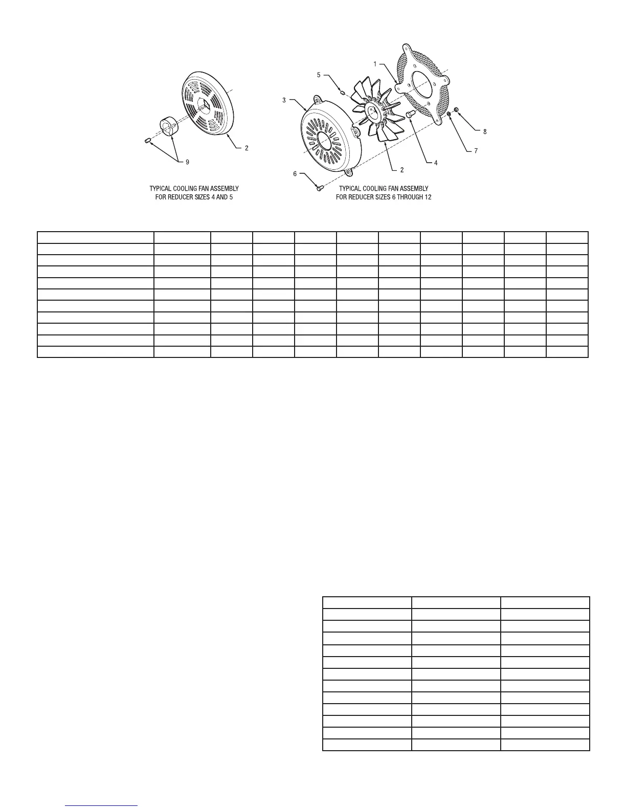
Figure 11 - Parts Identification
Table 7 – Cooling Fan Part Numbers
Description Ref. Number Quantity TA4207 TA5215 TA6307 TA7315 TA8407 TA9415 TA10507 TA12608
Cooling Fan Assembly ① ------ 1 904106 905106 906106 907106 907106 909106 910106 912106
Fan Guard Plate Assembly ② 1 1 ------ ------ 906519 906519 906519 909519 909519 912519
Fan Blade ② 2 1 904517 905517 906517 907517 907517 909517 910517 910517
Fan Guard Cover ② 3 1 ------ ------ 906521 906521 906521 909521 909521 909521
Mounting Bolt ② 4 4 ------ ------ 411294 411294 411294 411294 411294 411294
Fan Set Screw ② 5 2 ------ ------ 400086 400086 400086 400086 400086 400086
Cover Bolt ② 6 4 ------ ------ 411390 411390 411390 411390 411390 411390
Lockwasher ② 7 4 ------ ------ 419010 419010 419010 419010 419010 419010
Hex Nut ② 8 4 ------ ------ 407085 407085 407085 407085 407085 407085
Taper Bushing Assembly. ② ③ 9 1 117162 117092 ------ ------ ------ ------ ------ ------
① Assembly includes parts listed below marked ②
③ Set screws are included with taper bushing assembly.
BACKSTOPS
WARNING: To ensure that drive is not unexpectedly
started, turn off and lock out or tag power source before
proceeding. Remove all external loads from drive before
removing or servicing drive or accessories. Failure to
observe these precautions could result in bodily injury.
1. Remove backstop shaft cover and gasket, shown in Figure
10. These parts will not be reused. This cover is directly
opposite the extended end of the input shaft.
2. Clean the face of the gearbox to remove any gasket
material or contamination from the cover mounting surface.
It is important that contamination not get into the gearbox
or the backstop during the backstop installation/servicing
process.
3. Face reducer looking at the side from which the cover
was removed. Determine carefully the desired direction
of free rotation. It is important that the direction be
correctly determined because to reverse the direction after
the backstop is installed, it is necessary to remove the
backstop, turn it end-for-end and then reinstall it.
4. Match the arrow on the backstop inner race to the direction
of free rotation for the desired shaft. Note that reversing the
backstop end-for end changes the direction of the arrow.
The shaft will rotate in the same direction as the arrow on
the backstop.
5. If the backstop kit has a spacer ring included, install it onto
the shaft rst, adjacent to the bearing inner ring.
6. Install the backstop inner race and sprag cage assembly
onto the shaft. DO NOT remove the cage from the inner
race or the shipping strap from the sprag set at this time.
Insert the key into the inner race and mating shaft keyway.
These parts should slip onto the shaft easily, a light coating
of oil may assist in assembly. Do not use a hammer to
force the installation, damage can occur to the shaft and/
or the backstop. Slide the race against the spacer or the
shaft shoulder and install the retaining ring into the groove
in the shaft. Only use the supplied key, as it is specically
designed for each backstop.
7. Apply a thin coating of RTV silicone onto the gearbox
mating surface for the outer race (same as the cover area).
It is important to apply the sealant around the fastener
holes to prevent leakage. Do not allow excessive amounts
of silicone to enter the gearbox or to be applied to other
parts.
8. Install the outer race by gently rotating it opposite the shaft
rotation while pressing lightly inwards. Do not force the
outer race into position as backstop damage may occur.
Once the outer race is well piloted onto the sprag set,
remove the shipping strap from the sprag set by cutting it,
being careful not to let the outer race back off the sprags.
The outer race should slide easily into position with a slight
turning motion. A light coating of oil on the race inner
diameter may ease installation.
9. Align the fastener holes in the outer race with the mating
holes in the gearbox. Use the supplied grade 5 fasteners
and lock washers only. Torque the fasteners in an
alternating pattern per Table 8.
Table 8 – Backstop Fastener Torque Values
Reducer Size Fastener Size Torque in lb-ft
TA0107L 1/4-20 8 – 7
TA1107H 1/4-20 8 – 7
TA 2115H 1/4-20 8 – 7
TA3203H 1/4-20 8 – 7
TA4207H 1/4-20 8 – 7
TA5215H 5/16-18 17 – 15
TA6307H 5/16-18 17 – 15
TA7315H 3/8-16 30 – 27
TA8407H 5/16-18 17 – 15
TA9415H 3/8-16 30 – 27
TA10507H 3/8-16 30 – 27
TA12608H 3/8-16 30 – 27
 Loading...


