1
Basic Installation
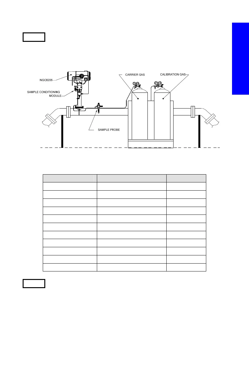
Step 1 Locate Suitable Installation Site
The NGC should be located close to the sample probe in an effort to
minimize the sample line length. See the table below for transport tubing
distances and lag times.
1/8” Transport Tubing Lag Time Considerations
Distance Conditioning Module Seconds
10’ (3.05 m) 2102023-XXX 36
20’ (6.10 m) 2102023-XXX 48
30’ (9.14 m) 2102023-XXX 60
50’ (15.20 m) 2102024-XXX 16
100’ (30.48 m) 2102024-XXX 23
150’ (45.72 m) 2102024-XXX 30
200’ (60.10 m) 2102024-XXX 36
250’ (76.20 m) 2102024-XXX 42
300’ (91.44 m) 2102024-XXX 50
350’ (106.68 m) 2102024-XXX 56
380’ (115.82 m) 2102024-XXX 60
Step 2 Mount the Unit
Mount the unit on a meter run, wall shelf, stand-alone pipe or inside a
cold weather enclosure.
NOTE: The NGC should not be connected to any section of pipeline
where cathodic protection exists.
The NGC has a grounding lug on the mounting neck of the enclosure.
This lug should be tied to a good earth ground with no smaller than
#12AWG wire.
Installation

 Loading...

