Subsequently the cable must be connected inside the inverter on the
Accessory Board
18
respecting the correspondence between the si-
gnals of the serial line.
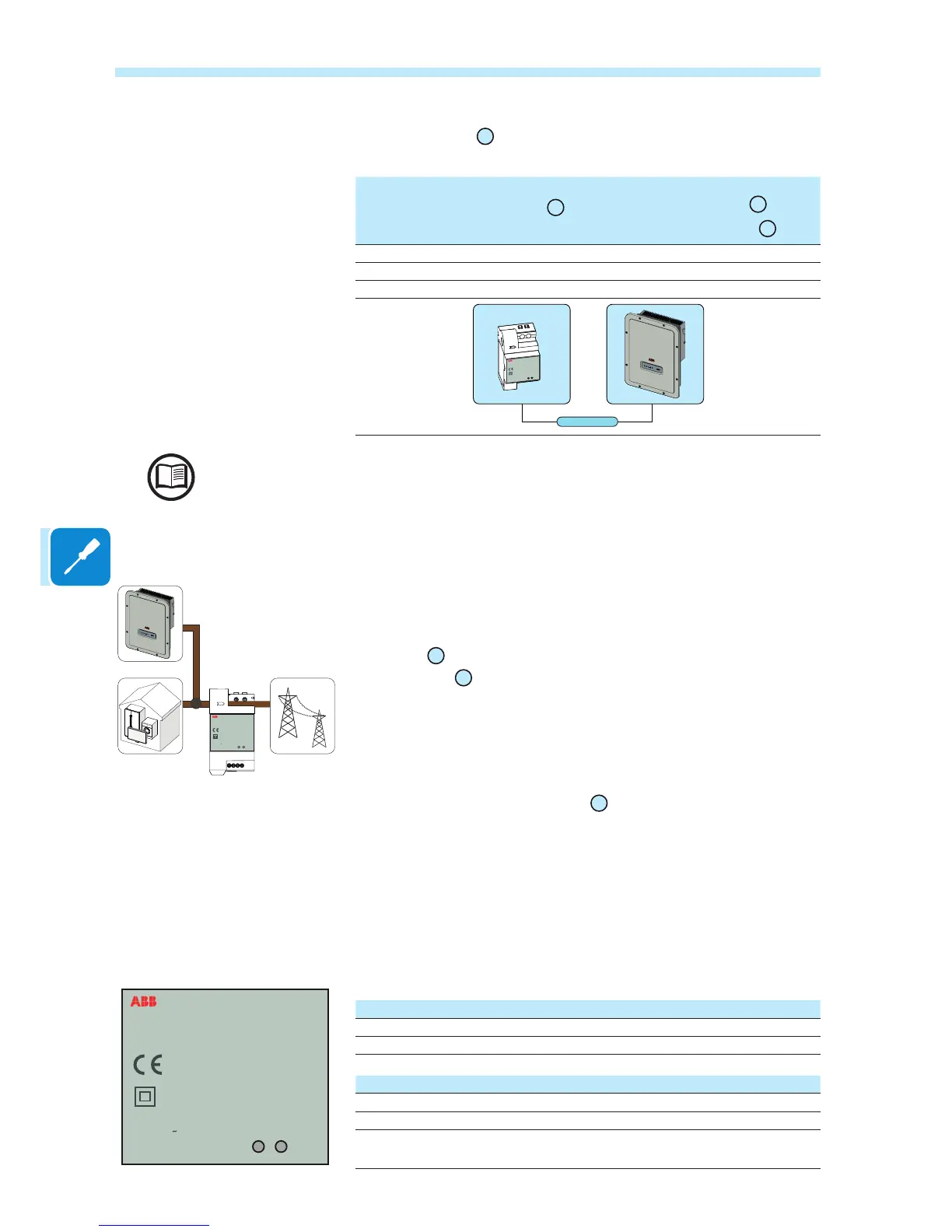
Serial line terminal block
of the REACT-MTR-1PH
57
Communication and control
signal terminal block
26
of the
Accessory Board
18
+T +T/R
-T -T/R
RTN RTN
RS485 LINE
REACT-MTR-1PH
SUTATS
ERUSAEM
INPUT :
110/230 V
50/60 Hz
10 mA max
To connect the serial cable inside the inverter, refer to the section “Connection of the RS485
line” in this chapter.
• Install the device on the DIN rail and ensure to trigger the xing sy-
stem on it
• Disconnect the phase cable (L) of the electric supply
• Insert the phase cable (L) through the hole (Ø8mm) on the REACT-
MTR-1PH
54
. The arrow corresponding to the hole for the feeding of
the line cable
55
, indicates the direction of insertion which must be
complied with for correct measurement of the current; in fact the direc-
tion of the arrow indicates the supply point of the electric energy (as
indicated in the diagram).
• Once the connection stage is nished, the correct installation of the
REACT-MTR-1PH must be veried
54
:
- Power the REACT-MTR-1PH while keeping the inverter off
- Action a load (of at least 50W) in the house so that the REACT-MTR-
1PH records drawing of current from the grid
- Check that the LED STATUS (red) is permanently on. This condition
indicates that a drawing from the grid is recorded and so that the rea-
ding of the direction of the current by the REACT-MTR-1PH is correct.
Here below is set out the behaviour of LEDs on the REACT-MTR-1PH:
MEASURE LED description
Permanent Green Serial communication absent or malfunctioning
Flashing Serial communication present
STATUS LED description
Permanent red Drawing of energy from the grid
Green (steady) Self-consumption (maximum exchange ±20W)
Flashing red and
green
Feeding energy to the grid
REACT-MTR-1PH
SUTATS
ERUSAEM
INPUT:
110/230 V
50/60 Hz
10 mA max
REACT-MTR-1PH
SUTATS
ERUSAEM
INPUT :
110/230 V
50/60 Hz
10 mA max
 Loading...


