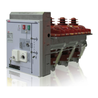
Consult circuit diagrams 1VCD400151 for fixed
circuit-breakers and 1VCD400155 for plug-in circuit-
breakers.
additional shunt opening release use 1 and/or 2
closing contacts “a”, thereby reducing the number
of auxiliary contacts available. Always check the
maximum number of contacts available with non-
standard equipment.
Auxiliary contacts –BGB1 conform to the following
standards/regulations/directives:
• IEC 62271-100
• IEEE C37.54
•
• Germanish Loyd regulation / vibrations envisaged
by the shipping registers
• UL 508
•
• RoHS Directive
7a Auxiliary contacts of circuit-breaker (-BGB1) for
15 kV versions
Electrical signaling of circuit-breaker open/closed
can be obtained with a group of 10, 16 or 20 auxiliary
contacts for the fixed version and 10 or 16 auxiliary
contacts for the plug-in version. The standard
equipment comprises 10 auxiliary contacts.
Note
The following are available with the standard group
of ten auxiliary contacts and the maximum number
of electrical accessories:
• for fixed circuit-breakers: three closing contacts
“a” for signaling circuit-breaker open and five
opening contacts “b” for signaling circuit-breaker
closed;
• for plug-in circuit-breakers: three closing contacts
“a” for signaling circuit-breaker open and four
opening contacts “b” for signaling circuit-breaker
closed.
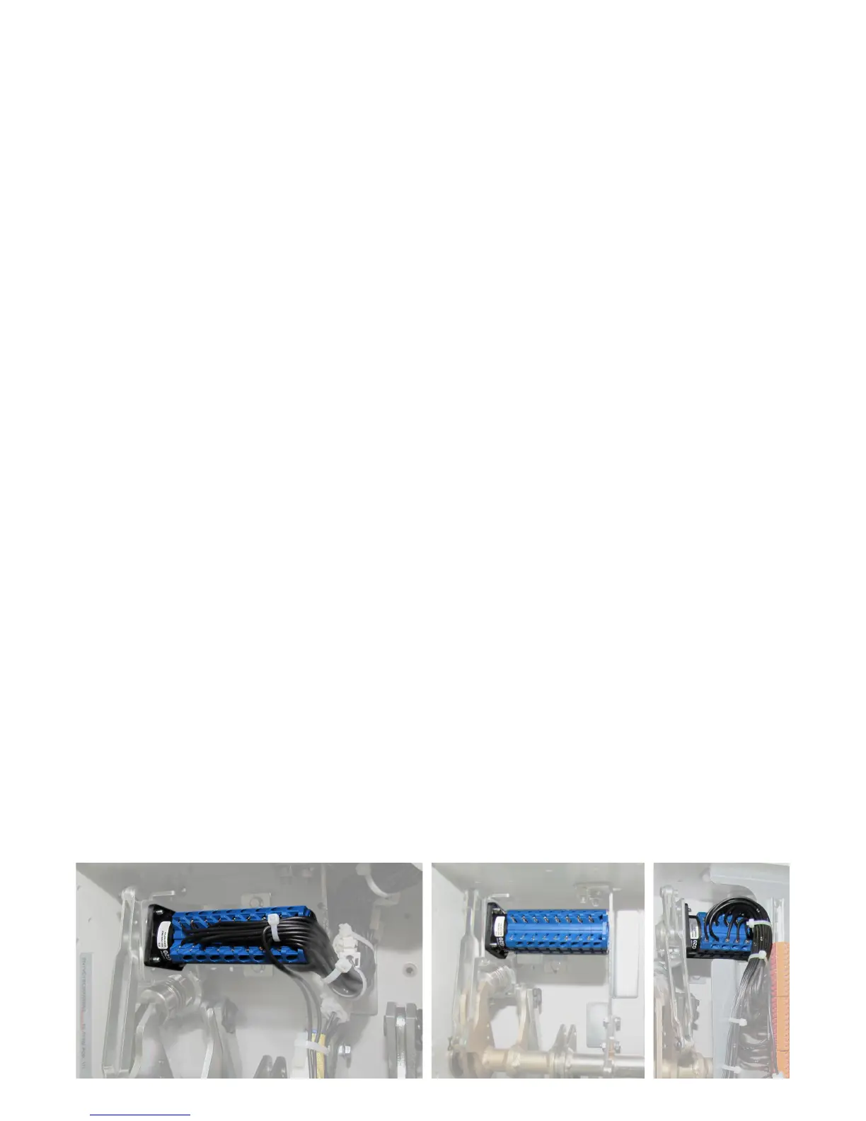
Circuit-breakers in the fixed version are available
with two finishing accessories (to be specified when
ordering):
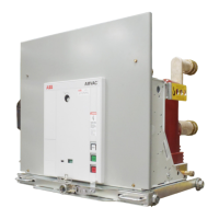
• non-wired auxiliary contacts; wiring to the
terminals of the contacts is at the customer’s
charge (photo below left; the terminal box to
which the other electrical accessories are wired is
at the top); ask for instructions 1VCD601204
(available in the main languages) which describe
how to remove, wire the auxiliary contact more
easily and fit the group of auxiliary contacts back
in place;
• auxiliary contacts already wired to the terminal
box (see photo)
—
5. Description
Accessories with the same number are alternatives.
16
 Loading...