Installaon instrucons for the OPEN SURF System and OPEN SURF System 2 above-water automac slaed safety cover - 4/22
4
1. Preparing the pool
1.1 Electric connecons and cable passages
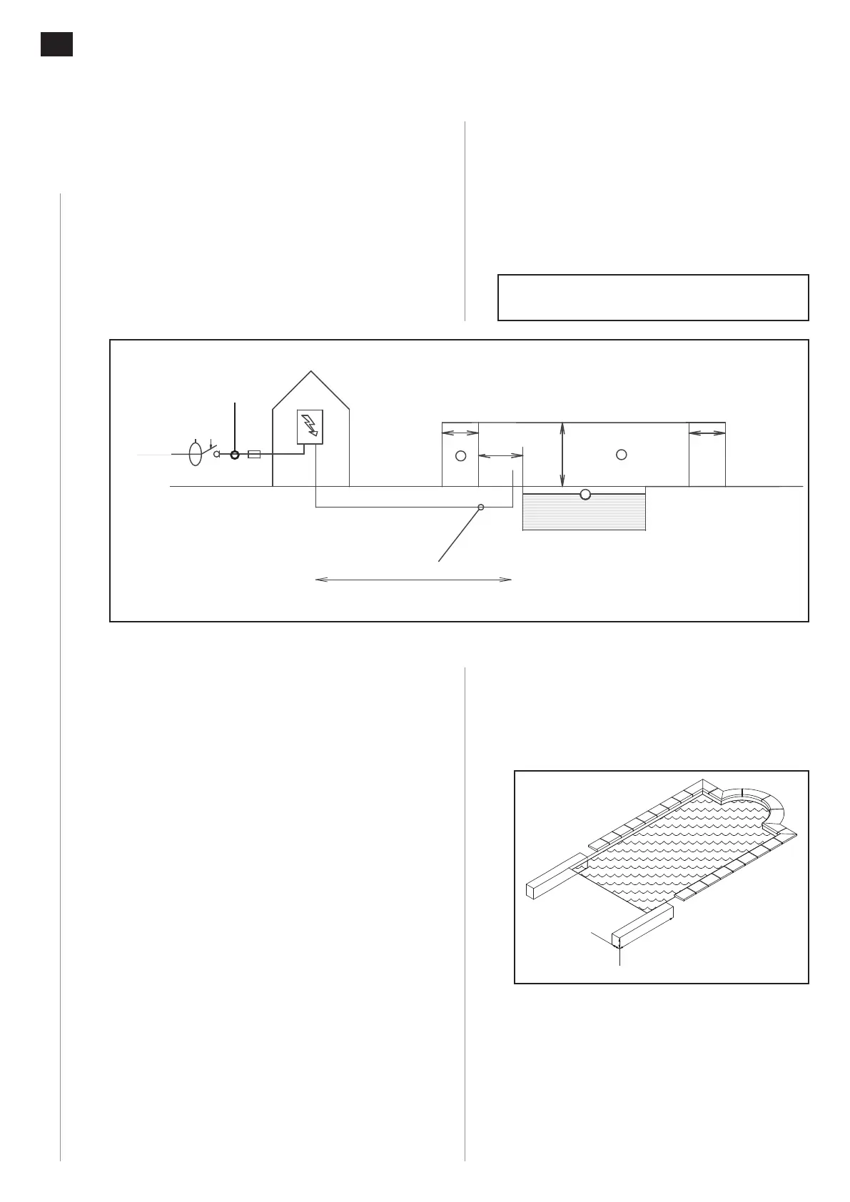
1.1.1 Power supply box (for a wired and a stand-alone
version)
Fig. 1
Prepare a 230 V power supply using R2V 3G2.5 mm²
(or Ro2V 3G2.5 mm²) cable for the electric box, which
must be installed outside volumes, ⓪, ①, and ②
in a dry area (technical room).
1.1.2 Electrical protecon
This power supply must be protected by a circuit
breaker or a 10 A fuse and a 30 mA ground fault
circuit breaker.
1.1.3 Sheaths
Prepare a connecon protected by a sheath for the
24 V DC power supply between the box and the
roller using 2 x 4 mm² if the cable is less than 15 m
long and using 2 x 6 mm² if the cable is between
15 m and 30 m long.
1.1.4 Cable passage
Separate cables transporng dierent voltages (24 V
and 220 V) and pass them freely placed in dierent
protecve sheaths and connect, removing all risks of
oxidaon and short-circuing, and in waterght and
accessible boxes located outside of volume 0 of the
swimming pool as per the NF C 15-100 standard.
1.1.5 Cable exit
Determine the cable output posion once the rails
have been installed and the stand posion is known.
1.1.6 Earthing
In compliance with the NF C15-100 standard, it is
imperave that all pools be ed with earthing in
compliance with standard requirements to evacuate
any stray currents that would exacerbate metal
oxidaon phenomena.
Consult the current electric standards and in
parcular NF C 15-100.
1.2 Building work
1.2.1 Concrete belt
Fig. 2
Provide for a concrete block using 350 kg/m
3
concrete, width 0.25 m, height 0.4 m of the length
(X) of the planned rail.
Fig. 2
x
25 cm
25 cm
x
40 cm
1.2.2 Overow
Fig. 3
Plan to control the water level at -12 cm below the
levelling course using a ø 50 mm overow which is
independent of the skimmers, and automac lling.
The absence of an operaonal overow compliant
with our recommendaons will void our guarantee.
Fig. 1
30mA
10A
2m
2.5m
1.5m
2
2
1
0
1.5m
D
230V 50Hz
0m< D <15m => 2 x 4mm2
15m< D <30m => 2 x 6mm2
230 V 50 Hz
30 mA
10 A
0 m < D < 15 m 2 x 4 mm
2
15 m < D < 30 m 2 x 6 mm
2
2 m
2.5 m
1.5 m
1.5 m
3 x 2.5 mm²
 Loading...