7/22 - Installaon instrucons for the OPEN SURF System and OPEN SURF System 2 above-water automac slaed safety cover
7
3. Assembling the OPEN SURF
3.1 Composion of the rails (SURF 1 and 2)
Fig. 7
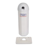
3.1.1 The rail is in 2 parts, one 2.5 m part which can be
recut to length and a 0.5 m part which ts into the
2.5 m part.
3.1.2 In excess of 3 m, the rail is composed of 3 parts, a
2.5 m part, a 3 m rail that can be recut to length and
a 0.5 m part that t together.
3.1.3 Important: aer a rail has been cut, check that
there are no burrs and protect the exposed cut part
of the stainless steel rail using an an-rust product.
Fig. 7
3.2 Dimensions to embed the rails
Fig. 8
Minimum width
cut to
embed the rail
on the bearing
block side
25 x 45 mm
4580
25
Spacing between rails
= pool + 700 mm
approx.
Minimum width
cut to
embed the rail on
the motor side
25 x 80 mm
Fig. 8
3.3 Assembling the rails (SURF 1 and 2)
3.3.1 1
st
rail
Fig. 9
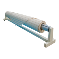
- Place the OPEN SURF System® symmetrically
on the pool and check that the roller tube is
perpendicular to the pool lengths (see g. 3). In
the case of a SURF System 2, the curved part of the
stand must be posioned on the pool side and the
"tail" (pointed part) on the deck side.
- Slide the rails under the wheels of the OPEN SURF.
- Advance the rail along the pool so that it is at least
260 mm from the edge.
- Fix the rails to the concrete block.
Fig. 9
Fig. 10
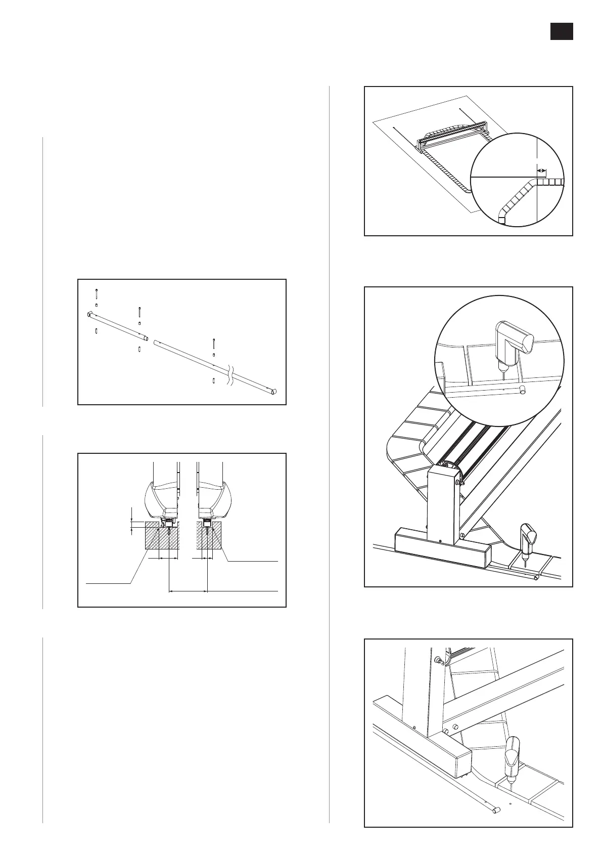
- Drill a hole using a 5 mm bit at the posion of the
rst hole in the rail on the pool side.
Fig. 10
Fig. 11
- Remove the rail to enlarge the hole to Ø 8 mm
and insert the anchor.
Fig. 11
Ø8 mm
 Loading...