EasyManuals Logo

Abus IPCB64521 Installation Manual

Abus IPCB64521
To Next Page IconTo Next Page
To Previous Page IconTo Previous Page
Page #8 background imageLoading...
Page #8 background image
8
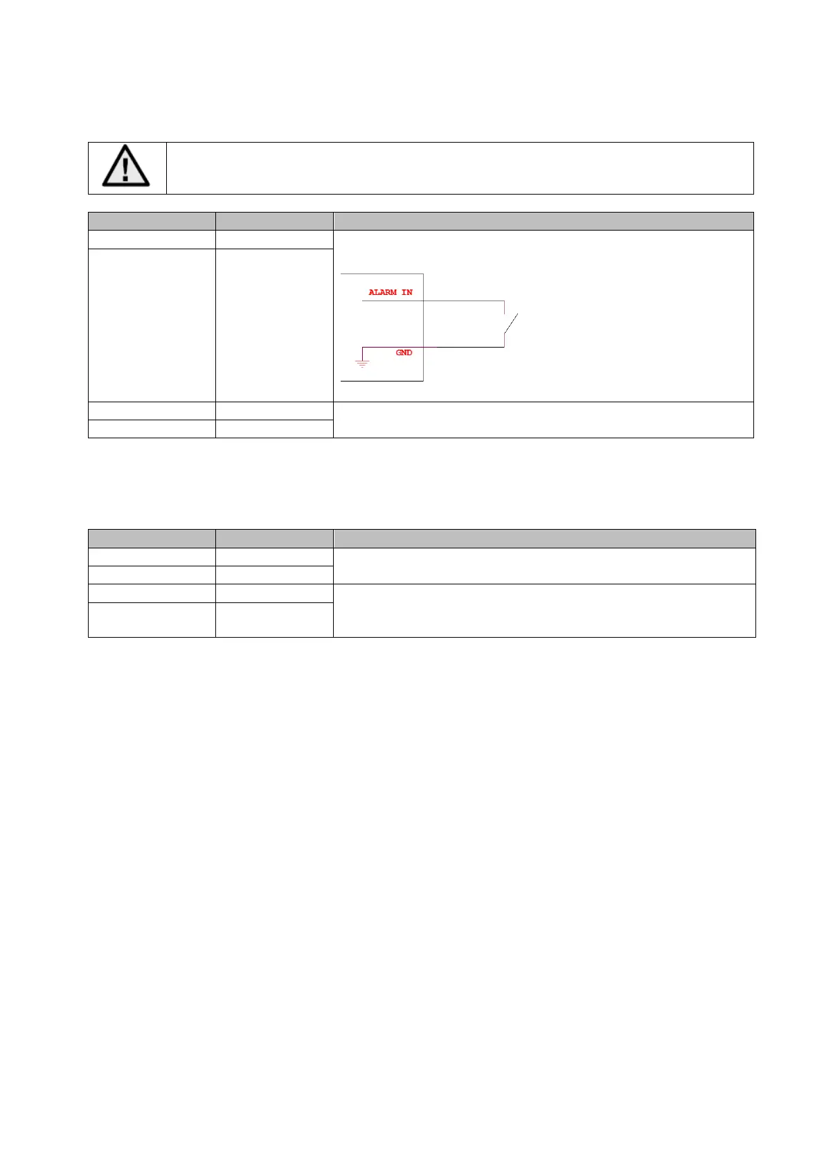
3.5 Schalteingang / Schaltausgang
Die maximalen Belastungswerte sind zu beachten, andernfalls kann die Kamera
irreparabel beschädigt werden.
Bezeichnung Anschlusshinweise
Schalteingang „IN“ Brücke zwischen „IN“ und „G“
„G“ (GND)
Schaltausgang „OUT“ 12 V DC / 24 V AC, max. 500 mA
„G“ (GND)
3.6 Audioeingang / Audioausgang
Bezeichnung Anschlusshinweise
A
udioeingang „IN“ LINE Interface
LINE: max. 3.3 Vss, Eingangsimpedanz 4.7KΩ
„G“ (GND)
A
udioausgang „OUT“ Impedanz: 100 Ω
Frequenzgang: 20 Hz – 20 kHz
A
usgangsamplitude: max. 3.3 Vss
„G“ (GND)

Other manuals for Abus IPCB64521

Questions and Answers:

Question and Answer IconNeed help?

Do you have a question about the Abus IPCB64521 and is the answer not in the manual?

Abus IPCB64521 Specifications

General IconGeneral
BrandAbus
ModelIPCB64521
CategorySecurity Camera
LanguageEnglish

Related product manuals