17
3.5 Switching input/output
The maximum load values must be observed, otherwise, the camera may be
irreparably damaged.
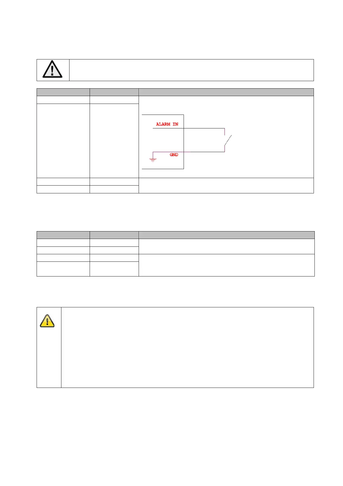
Description Connection information
Switching input „IN“ Bridge between „IN“ and „G “
„G“ (GND)
Switching output „OUT“ 12 V DC / 24 V AC, max. 500 mA
„G“ (GND)
3.7 Audio input / audio output
Description Connection information
udio input „IN“ MIC / LINE Interface
LINE: max. 3.3 Vpp, input impedance 4.7 kΩ
„G“ (GND)
udio output „OUT“ Impedance: 100 Ω
Frequency range: 20 Hz – 20 kHz
Output amplitude: max. 3.3 Vss
„G“ (GND)
3.8 Notes to the usage of internal IR LEDs
The IR range is strongly dependent on the environmental conditions. If the area in the
camera's field of view reflects poorly or if there are no objects within the max.
illumination range, the brightness of the video image at night may be too low. This will
result in poor usability of the video image.
In addition, when installing the camera it must be ensured that no objects are located in
close proximity to the camera's field of view (e.g. roof gutter or wall). These objects can
reflect back the IR light, resulting in circular fading on the video image in the opposite
direction to the object.
The IR range might be reduced as well by strong absorbing surfaces (e.g. asphalt).