10
ASSEMBLY INSTRUCTIONS (Continued)
INSTALL THE OPTIONAL
CARRIAGE BELLOWS (if ordered)
Optional carriage bellows are available to keep excess
grindings, dirt, etc. out of the carriage assembly. To
install the two bellows:
1. Remove the left and right outside leg panels.
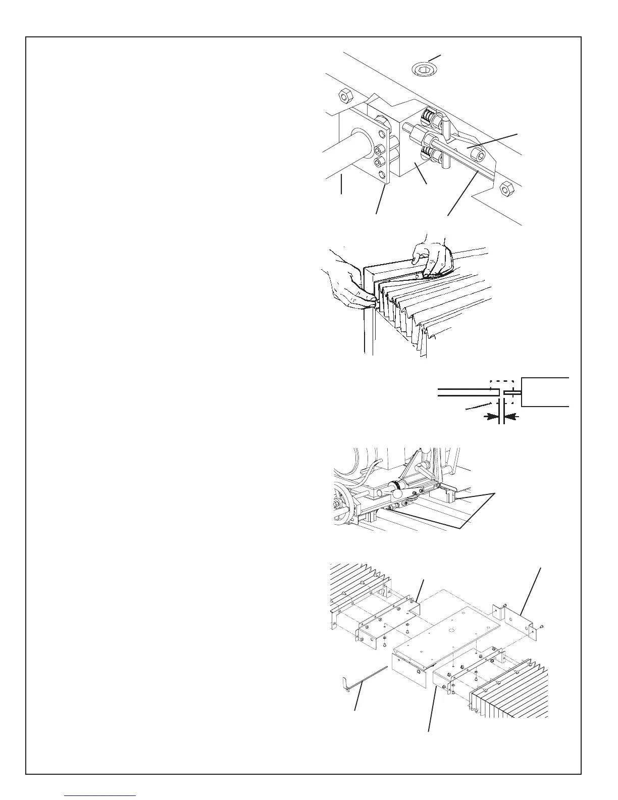
2. Remove the shaft seal on each side of the linear
actuator. See FIG. 9. NOTE: When the bellows are
used, the shafts don't get lubricated and the seals
would run dry. They would then become noisy and
not operate properly. To remove the seals:
a. Crank the carriage all the way toward the
front (that is, toward the operator's position).
b. Remove the actuator mounting screw on top
of the carriage. See FIG. 9. Loosen the
setscrew on the collar that holds the actuator
release lever in place (this is located behind
the flap by the release lever handle). Remove
the actuator release lever. (Keep track of all
hardware. See page 40 for exploded view.)
Then push the carriage toward the right end of
the Grinder.
c. Loosen the two set screws in the bearing
pillow block at each end of the drive shaft.
Loosen the two set screws in the drive
coupling at the right end of the carriage.
d. Slide the drive shaft out the left end of the
machine.
e. Remove the shaft seals from the actuator -
two screws each.
f. Reinstall the drive shaft. The right end of the
shaft (inside the coupling) should be 1/8 - 1/4"
[3 to 6.5 mm] from the end of the motor
shaft (See Fig 10A). Retighten all set screws.
g. Push the carriage back to the left, and
reattach the actuator with the mounting
screw. See FIG. 9.
3. Remove the two rail wiper brackets from each side
of the carriage - two screws each. (See Fig11A)
4. Attach the outer end of each bellows to the Grinder
leg panel. See FIG. 10. Use six bolts, and hex
nuts, at each end. The bolt heads go on the bellows
side of the brackets.
5. Attach the right and left brackets to the underside of
the carriage using two 1/4" button head screws and
lockwashers on each side. (See Fig 11) Then attach
the rear protective plate to the brackets just installed
using two 1/4" screws and locknuts. Re-install the
actuator release lever. Last attach the bellows to the
brackets with the bolt heads on the bellows side of
the brackets.
6. Press the bellows down until it snaps onto the
carriage rails.
7. Reattach the left and right outside leg panels.
FIG. 9
Actuator Mounting
Screw (under the rubber
splash guard)
Drive Shaft
Actuator Bar Assembly
Linear Actuator
Seal Plate
Actuator Release Lever
Drive
Shaft
Flexible
Coupling
Traverse
Motor
1/8 to 1/4 in.
FIG. 10A
FIG. 11
Left Bellows
Bracket
Right Bellows
Bracket
Rear Plate
Actuator
Release
Lever
FIG. 10
FIG. 11A
Wiper
Brackets
 Loading...