23
ADJUSTMENTS (Continued)
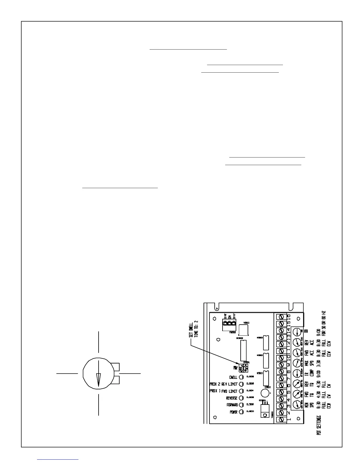
POTENTIOMETER ADJUSTMENTS TRAVERSE DRIVE CONTROL (TDC)
Min. Speed--Factory set at full (CCW) 8:30. Do not change this setting.
(Right Traverse) Forward Torque--Factory set at full (CW) 4:30. Do not change this setting.
(Left Traverse) Reverse Torque--Factory set at full (CW) 4:30. Do not change this setting.
IR COMP--Factory set to 9:00. IR COMP is current (I) resistance (R) compensation (COMP).
IR COMP adjusts the output voltage of the drive which balances load to motor RPM. Regulation of a traverse
motor may be improved by slight adjustment of the IR COMP trim pot clockwise from its factory-set position.
Overcompensation causes the motor to oscillate or to increase speed when fully loaded. If you reach such a
point, turn the IR COMP trim pot counterclockwise until the symptoms disappear.
Max. Speed--Set at 3:30 for maximum voltage of 90 Volts DC to the traverse motor. When voltage is above 90
volts DC, the traverse motor will start to pulsate and not run smoothly.
(Right Traverse) Forward Acceleration--Factory set at full (CCW) 8:30. Do not change this setting.
(Left Traverse) Reverse Acceleration--Factory set at full (CCW) 8:30. Do not change this setting.
(DB) Dead Band is the potentiometer setting for the 50 or 60 Hz cycle control. Factory set to 9:00, works for
both 50 and 60 Hz. Do not change this setting.
Calibrating the DWELL TIME rotary DIP switch adjusts the amount of time the process remains in the stop
position after a limit switch is actuated. The DWELL TIME range is adjustable from 0 - 4 seconds. A DIP
switch setting of 0 sets the DWELL TIME to 0 seconds, while a setting of 8 sets the DWELL TIME to 4 sec-
onds. Dwell time is preset to #2 setting for a 1 second dwell time when reversing at each end of stroke.
Diagnostic LED's indicate the function that is currently being performed:
* POWER indicates that ac power is being applied to the control.
* FORWARD indicates that the process is running in the forward direction (traversing left).
* REVERSE indicates that the process is running in the reverse direction (traversing right).
* PROX 1 FWD LIMIT lights when the forward limit switch is actuated (left prox).
* PROX 2 REV LIMIT lights when the reverse limit switch is actuated (right prox).
3:00
12:00
9:00
Potentionmeter
Clock Orientation
6:00
 Loading...