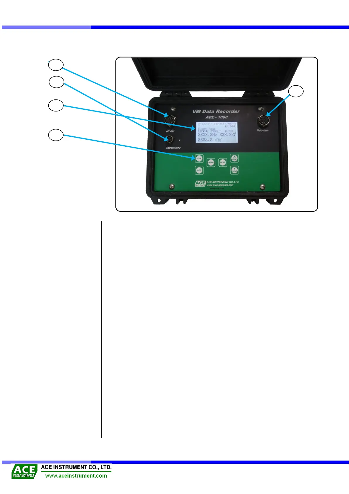
1-4 Name & Explanation for each part
① It shows date of measurement, measurement mode (Sweep, Unit), measured data and
temperature, remained battery, and saved ID.
② - [ON] : Turn on the power
- [OFF] : Turn off the power.
- [MENU] : Useful to set a readout unit and measuring mode.
- [ENTER] : Choose and set measurement modes (Sweep, Temperature sensor,
Measurement unit, Data saving, Contrast, automatic power) and move
onto the next stage.
- [▲/LIGHT] : Useful to turn on/off the Backlight and to change options in Setting mode
of MENU Button.
- [▼/SAVE] : Useful to save data and to Data and to change options in Setting mode of
MENU Button.
③ Connect to a jumper cable to measure the frequency.
④ It is useful to download or delete the saved data from the computer, or to set the readout
unit.
⑤ Useful to charge the built-in battery. If it is fully charged, the lamp is off, while it is off
during recharging.
(It takes about 4 hours to charge the battery.)
A VW type sensor is used to connect with a clip.
(In the above figure it connects to Transducer Connector, No. ③)
It is to connect a VW readout unit to the computer.
(In the above figure it connects with RS-232 Connector, No. ④)
It is to charge the battery, which is installed in the VW readout unit.
(In the above figure it should be connected to charger connector, No. ⑤)