6
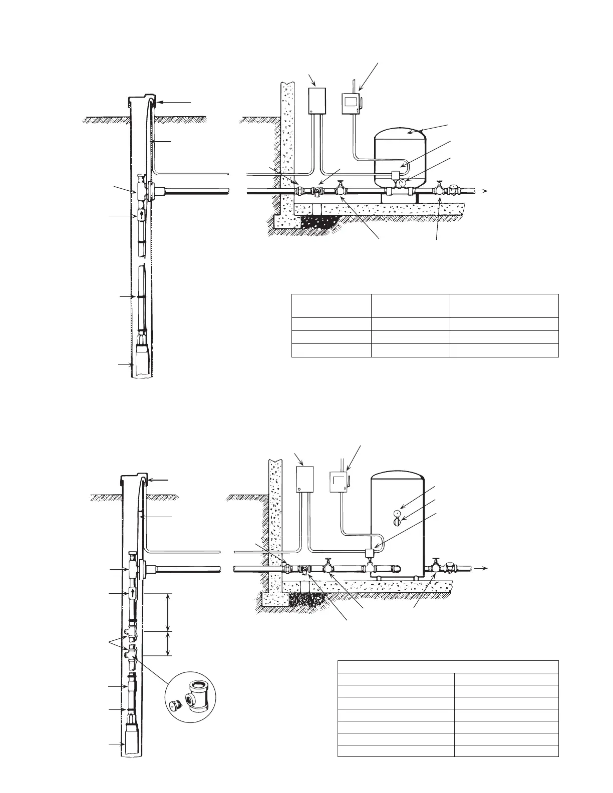
Ventilated
well cap
Submersible
cable
Pitless
adaptor
Check
valve
Tape cable
to pipe
Pump
Submersible
motor control
(3 wire models)
Electrical disconnect
Pre-charged tank
Pressure switch
Pressure gauge
To house servic
Relief valveUnion
Gate valve
Pitless
adaptor
Check valve
Bleeder orifice
& tee
Pipe coupling
Tape cable
to pipe
Pump
Ventilated
well cap
Submersible
cable
Union
Submersible
motor control
(3 wire models)
Electrical disconnect
Pressure gauge
Air volume control
Pressure switch
To house servic
Gate valve
Relief valve
2 ft.
(.6m)
See table
Figure 11 – Typical Pre-Charge Tank Installation
Figure 12 – Typical Standard Tank Installation
CUT IN CUT OFF Pre-charge Tank
PSI (kPa) PSI (kPa) PSI (kPa)
20 (137.9) 40 (275.8) 18 (124.2)
30 (206.8) 50 (344.7) 28 (193.1)
40 (275.8) 60 (413.7) 38 (262)
CHECK VALVE DISTANCE TO TOP BLEEDER ORIFICE
TANK SIZE/GALLON (L) DISTANCE FT. (M)
42 (159) 2 (.6)
82 (310.4) 3 (.9)
120 (454.2) 5 (1.5)
220 (832.7) 5 (1.5)
315 (1192.3) 10 (3)
525 (1987.1) 15 (4.6)