7. Assembly and Disassembly Procedures (continued)
Part Number
Part Name
7115240121P0A SCR EW _M4*12_DOU BLE W ASHIER 4 Screw Size=M4x12; Torque=12~14KGF .CM
7740412200P0A STAN D_BASE_ACER_AL1717_#6800_ABS 94HB 1 -
7742612091P0A
STAN D_CO VER _#6800_ABS 94HB _ABS 94HB_A CER
R17BN W
1-
7749600200P0A TAPE_MASKING_PACKING_25mm (w)x45m_LITEON 2 -
7730203550P0A CAR D_SC REEN PRO TECTO R_ACE R_T17AA_A L1716W 1 -
7735431685P0A
LABE L_VISTA(W ORKS )_CM YK_25.4x11.2_LENOV O
T15AN
1-
7749003210P0A
BAG_LDPE+EPE_ORDINARY_ALL
MO DEL_L680xW 550mm xH0.55mm
1-
7749003190P0A BAG _PE_O RDINARY _FOR ACER _L300xW300xT0.05 mm 1 -
7749106560P0A
CUSHION FOAM_EPS_ACER-AL1716W_2160SE TS_
L<(>&<)>R_472x117x398(H)
2-
7749600200P0A TAPE_MASKING_PACKING_25mm (w)x45m_LITEON 4 -
Q'ty Remark
Spare Parts List
S20
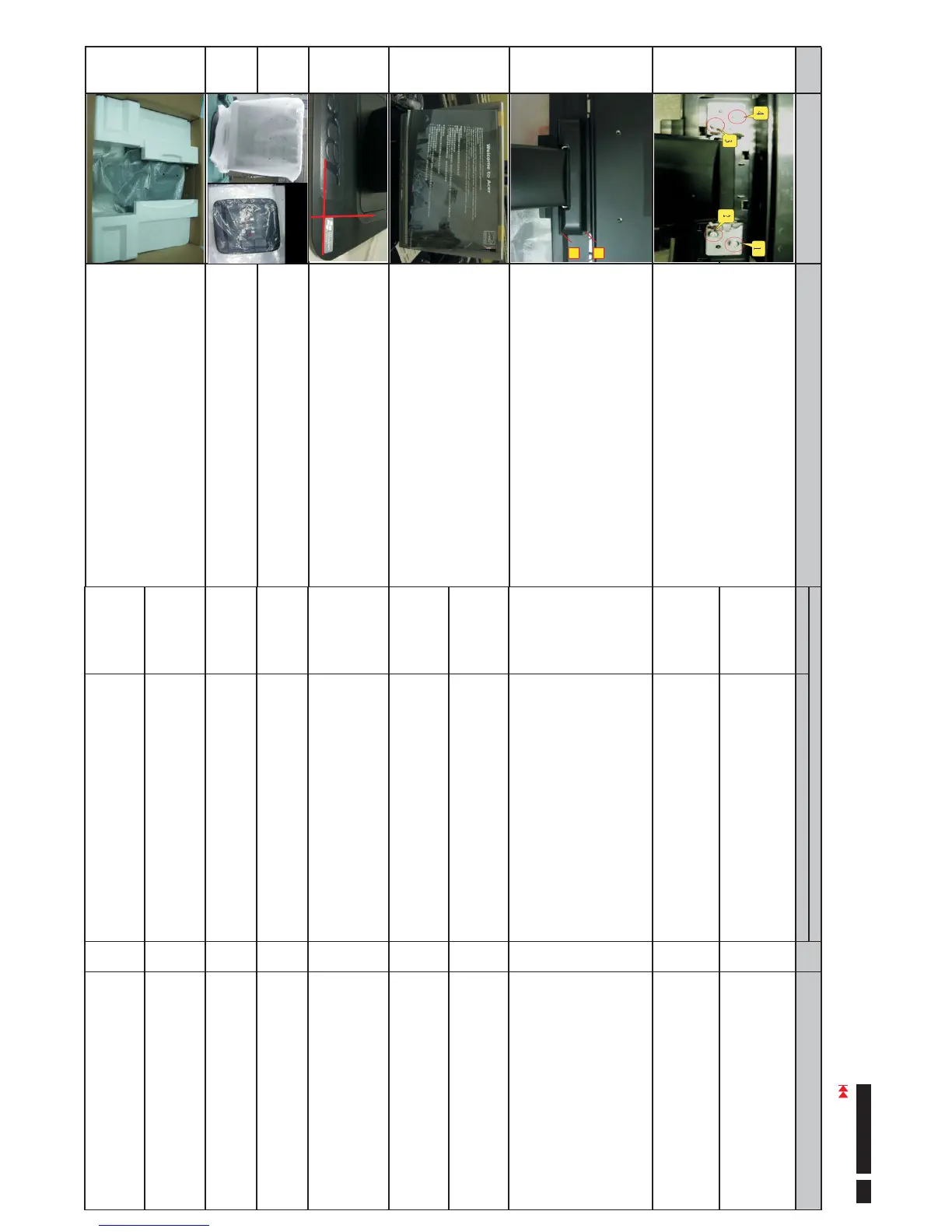
Lock the stand cover according to the order of the num ber
1~2 till two pa rts firm ly a ttac he d.
S22
Stick a Vista label on the rear side of F ront Bezel (nearby
Stand Base).
S23
Take a LDPE+EPE bag (L680xW550mmxH0.55mm ) to
cover the LCD monitor.
S24
Take a PE bag (L300xW300xT0.05 mm) to cover the Stand
Base.
ProceduresSteps Photo
Take two cushion foams; one is held the left side of LCD
monitor, and another is held the right side.
S25
S21
Turn over the LCD module (screen faced down), then take a
Stand Base and put it on specific positions as photo left. Use
a Phillips - hea d scre wdr iver ass e mb led the S t and base to
LCD module with 4 screws.
S19
Stick a Screen Card on the Front Bezel with two tapes.
1
2
Line 1
Line 2
Go to cover page
44
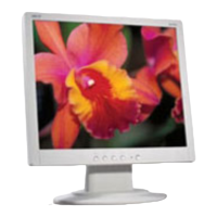
ACER AL1716W
 Loading...