7. Assembly and Disassembly Procedures (continued)
Part Numbe r Part Name
7115240121P0A SCREW_M 4*12_DOUBLE WASHIER 4 Screw Size=M4x12; Torque=12~14KGF.CM
7740412200P0A STAND_BASE_ACER_AL1717_#6800_ABS 94HB 1 -
-- --
-- --
-- --
7737517400P0A FC ASSY_#6790/#6810_ABS94V0_ACER_T17BNHW 1 -
5113800899P T17BNHW -G1(99)_ACER_FUNCTION KEY BD 1 -
7140130061P0A SCREW_M ACHINE_W ITHOUT_NINDING_M3_6L_BLA 2 Screw Size=M3x6; Torque=6~8KGF.CM
Spare Parts Usage
Q'ty Remark
S6
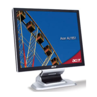
Turn over the LCD m onitor (screen faced up).
S7
Place cloth on the panel where you are working on to protect
the panel. Continuely, wedge your finger between the front
bezel and the panel, then pry up on the front bezel to
disengage the locking m echanism.
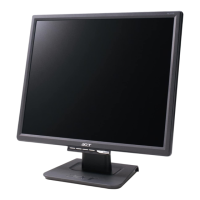
S8
Work your way along the front bezel to disengage all the
locking mechanism.
S9
Once all the locking m echanisms are release from front bezel;
remove the bezel carefully.
Us e a Phillip s - head screwdriver unscrewed number 1~2 screws
to release the Key Function board from the Front Bezel.
S10
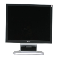
S5
Us e a Phillip s - head screwdriver unscrew 4 screws to release
the stand base.
Steps Photo
Procedures
2
1
Key Function cable
Go to cover page
47
ACER AL1716W
 Loading...