37
Connector Information
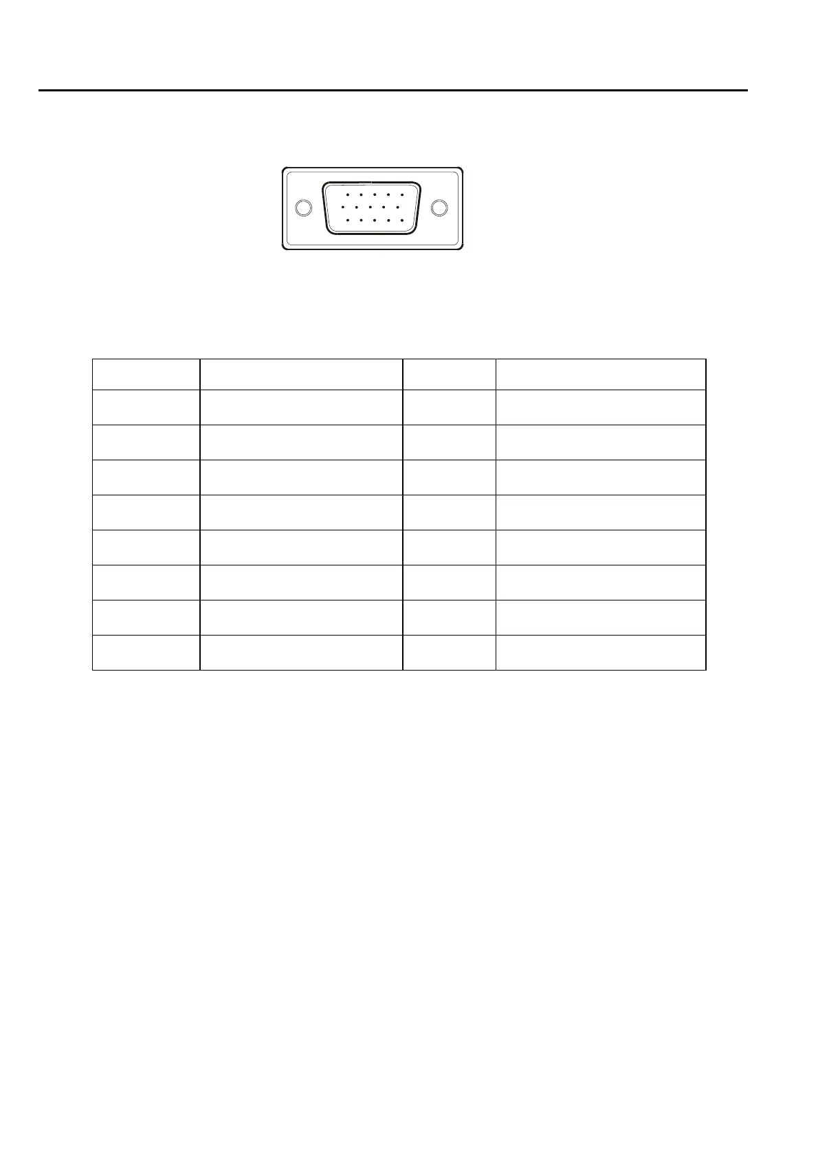
The following figure shows the connector locations on the monitor board:
15
6
10
11 15
15 – Pin Color Display Signal Cable (D-sub)
PIN NO. DESCRIPTION PI N NO. DESCRIPTION
1. Red 9. +5V
2. Green 10. Logic Ground
3. Blue 11. Monitor Ground
4. Monitor Ground 12. DDC-Serial Data
5. DDC-Return 13. H-Sync
6. R-Ground 14. V-Sync
7. G-Ground 15. DDC-Serial Clock
8. B-Ground
Chapter 5

 Loading...