R
Robert ParkerJul 30, 2025
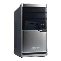
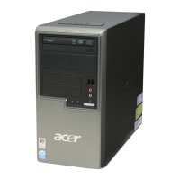
How to fix Acer ASPIRE M5910(G) when system will not power on?
- LlauragibsonJul 30, 2025
If your Acer Desktop isn't powering on, ensure the power cable is securely connected to both the system and the AC power source. Also, verify that the voltage selector switch is set to the appropriate voltage.