Do you have a question about the Acer Aspire M1610 and is the answer not in the manual?
Details the operating system, processor, chipset, PCB, memory, graphics, and PCI specifications.
Lists supported CPU types and their specifications.
Details the memory controller, supported memory types, and configurations.
Provides clock speeds for various system components.
Describes the SIS672 Host/Memory Controller and its features.
Details the SiS 968 Media I/O component and its functions.
Explains the features of the Super I/O chip (IT8718F).
Describes the integrated audio subsystem and its components.
Details the Realtek LAN controller and its specifications.
Lists USB specifications, ports, and connectors.
Describes the IEEE 1394 controller and its capabilities.
Lists the available expansion slot types and quantities.
Details the connectors and ports on the rear I/O panel.
Explains power management modes and features.
Describes the Super I/O's hardware monitoring capabilities.
Details the LPC bus implementation for the BIOS.
Specifies the default SPI bus used for the BIOS.
Instructions on how to access and navigate the BIOS setup utility.
Displays detailed system information such as product name, serial number, and BIOS version.
Configures basic system settings like date, time, and drive parameters.
Configures settings for the primary IDE channel master device.
Configures settings for the primary IDE channel slave device.
Configures settings for the secondary SATA channel master device.
Adjusts advanced system features like boot order and virus warnings.
Configures CPU-specific features like limit CPUID MaxVal and C1E.
Sets the boot order for installed hard disk drives.
Fine-tunes graphics and memory hole settings for performance.
Manages settings for the integrated graphics controller, including memory allocation.
Enables or disables onboard peripherals like IDE, PCI, and Super IO devices.
Configures serial ATA mode and IDE transfer settings for onboard IDE devices.
Manages onboard PCI devices including USB, audio, and LAN controllers.
Configures serial ports, parallel ports, and other Super IO functions.
Sets ACPI functions, suspend types, and wake-up events for power saving.
Configures PCI/VGA palette snoop and PCI Express settings.
Monitors system voltages, temperatures, and fan speeds.
Adjusts clock frequencies and voltages for system components.
Loads default BIOS settings to restore factory configurations.
Sets BIOS passwords for system security.
Saves current BIOS settings to CMOS and exits the setup utility.
Discards all changes and exits the BIOS setup utility.
Provides essential information and precautions before starting disassembly.
Step-by-step guide for disassembling the Aspire M1610/Veriton M261.
Step-by-step guide for reassembling the computer after service.
Diagram showing the location of jumpers and connectors on the mainboard.
Explains how to set jumpers for correct mainboard configuration.
Details the pinout and function of front panel USB connectors.
Details the pinout and function of front panel audio connectors.
Details the pinout and signal names for front panel 1394 connectors.
Details the pinout and signal names for the internal speaker header.
Details the pinout and signal names for the 3-pin system fan connector.
Details the pinout and signal names for the 4-pin CPU fan connector.
Explains the jumper settings for clearing the CMOS.
Details the pinout and signal names for the chassis intrusion detection header.
Details the pinout and signal names for the J3 connector.
Details the pinout and signal names for the J4 connector.
Details the pinout and signal names for the SPDIF output header.
Details the pinout and signal names for the IRDA connector.
Details the pinout and signal names for the COM2 serial port header.
Diagram showing the exploded view of the Aspire M1610 computer components.
Diagram showing the exploded view of the Veriton M261 computer components.
| Tcase | 73.3 °C |
|---|---|
| Bus type | FSB |
| Stepping | M0 |
| Processor cache | 1 MB |
| Processor cores | 2 |
| System bus rate | - GT/s |
| Processor family | Intel® Pentium® |
| Processor series | Intel Pentium E2000 Series for Desktop |
| Processor socket | LGA 775 (Socket T) |
| Processor codename | Conroe |
| Processing Die size | 77 mm² |
| Processor frequency | 2 GHz |
| Processor cache type | L2 |
| Processor lithography | 65 nm |
| Processor manufacturer | Intel |
| Processor front side bus | 800 MHz |
| Processor operating modes | 64-bit |
| ECC supported by processor | No |
| Thermal Design Power (TDP) | 65 W |
| CPU multiplier (bus/core ratio) | 10 |
| Number of Processing Die Transistors | 105 M |
| Internal memory | 3 GB |
| Internal memory type | DDR2-SDRAM |
| Maximum internal memory | 4 GB |
| HDD speed | 7200 RPM |
| HDD interface | SATA |
| Card reader integrated | Yes |
| Total storage capacity | 320 GB |
| Discrete graphics card model | NVIDIA® GeForce® 8400 GS |
| Maximum graphics card memory | 0.256 GB |
| Audio system | High Definition Audio 7.1 |
| Product type | PC |
| Trial software | Microsoft Office 2007, Norton Internet Security 2007, eSobi v2, 0 Lite |
| Bundled software | Microsoft Works 8.5, Adobe Reader 7.0, Acer Arcade Live, Quick Burning (NTI CD-Maker Gold), Acer Empowering Technology |
| Operating system installed | Windows Vista Home Premium |
| USB 2.0 ports quantity | 6 |
| Firewire (IEEE 1394) ports | 1 |
| Networking features | Gigabit Ethernet |
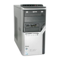
| Chassis type | Tower |
| Processor code | SLA8Y |
| Processor ARK ID | 31733 |
| Processor package size | 37.5 x 37.5 mm |
| Depth | 420 mm |
|---|---|
| Width | 180 mm |
| Height | 360 mm |