Do you have a question about the Acer Aspire T180 and is the answer not in the manual?
Provides a general overview of the system's features and capabilities.
Details the specifications of various system components like processor, memory, and graphics.
Visual guide to motherboard components and their locations.
Functional overview of the system's architecture and component interconnections.
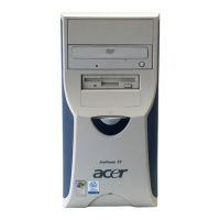
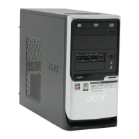
Front view and description of components on the Aspire T180 computer.
Rear view and description of ports and connectors on the Aspire T180.
Front view and description of components on the AcerPower M8 computer.
Rear view and description of ports and connectors on the AcerPower M8.
Describes standard input/output devices like mouse, keyboard, and speakers.
Information regarding the connection and optional nature of system speakers.
Explains the Acer eRecovery utility for system backup, restore, and software reinstallation.
Outlines the process for restoring the system using disc-to-disc recovery without a CD.
Lists detailed technical specifications for the system's hardware components.
Instructions on how to access and navigate the BIOS setup utility.
Displays system details such as model name, serial number, and BIOS version.
Covers basic system configuration settings like date, time, and drive parameters.
Details advanced BIOS settings for system optimization and customization.
Defines the boot sequence for removable media devices in BIOS.
Sets the boot order for installed hard disk drives in BIOS.
Configures the boot sequence for CD-ROM drives in BIOS.
Allows adjustment of critical timing parameters for the motherboard chipset.
Manages the configuration of all onboard peripherals and controllers.
Enables or disables various onboard hardware devices like USB, Audio, and LAN.
Configures settings for onboard I/O controllers, including serial and parallel ports.
Configures system power management features and ACPI settings.
Manages Plug and Play and PCI resource allocation.
Monitors system component status, including temperature, voltage, and fan speed.
Allows setting or disabling BIOS supervisor and user passwords.
Resets BIOS and chipset features to factory default values.
Saves current BIOS settings and exits the setup utility.
Discards any changes made in the setup utility and exits.
Provides essential precautions and tools required before disassembling the computer.
Step-by-step instructions for safely disassembling and reassembling the computer.
Guidance on understanding the Power-On Self-Test process.
Identifies critical check points within the Power-On Self-Test.
A list of common error messages encountered during POST.
Helps diagnose system issues by correlating symptoms with potential causes.
Explains how to set jumpers for correct system configuration on the motherboard.
Identifies jumper locations and their default or protective settings.
Guides on connecting internal components like fans and speakers to the motherboard.
Details the pinout and signals for the ATX power connector.
Details the pinout and signals for the ATX 12V power connector.
Describes the pinout for front panel switches, LEDs, and audio connectors.
Pinout diagram for the floppy disk drive (FDD) connector.
Pinout diagrams for the IDE (Integrated Drive Electronics) connectors.
Instructions for connecting various optional external devices.
Pinout details for the auxiliary audio input connector.
Pinout information for the front panel USB headers.
Pinout diagram for the front panel audio header.
Pinout details for the Infrared (IRDA) header.
Pinout information for the SPDIF digital output header.
Pinout details for the Serial ATA (SATA) connectors.
Pinout diagram for the onboard IEEE 1394a header.
Pinout diagram for the onboard serial port (COM2) header.
Illustrates and describes the various ports on the rear of the computer.
Pinout details for the PS/2 keyboard and mouse connectors.
Pinout diagram for the COM1 serial port header.
Pinout diagram for the parallel port (LPT) connector.
Pinout details for the combined USB and LAN connector.
Pinout diagrams for various USB connectors.
A visual breakdown of the computer's components with numbered labels.
Lists Field Replaceable Units (FRUs) for parts ordering and repair (updates pending).
| Form Factor | Tower |
|---|---|
| Power Supply | 250W |
| Chipset | NVIDIA nForce 430 |
| Storage | 80 GB SATA |
| Graphics | Integrated NVIDIA GeForce 6100 |
| Optical Drive | DVD-ROM / DVD-RW |
| Operating System | Windows Vista Home Basic |
| Audio | Integrated 5.1 channel audio |
| Networking | 10/100 Ethernet |
| Expansion Slots | 1 x PCI Express x16, 2 x PCI |
| Front Ports | 2 x USB 2.0 |
| Rear Ports | 4 x USB 2.0, 1 x Ethernet, 1 x VGA |