1-20 Disassembly Procedures
Mainboard Removal 0
Prerequisite:
LCD Module Removal
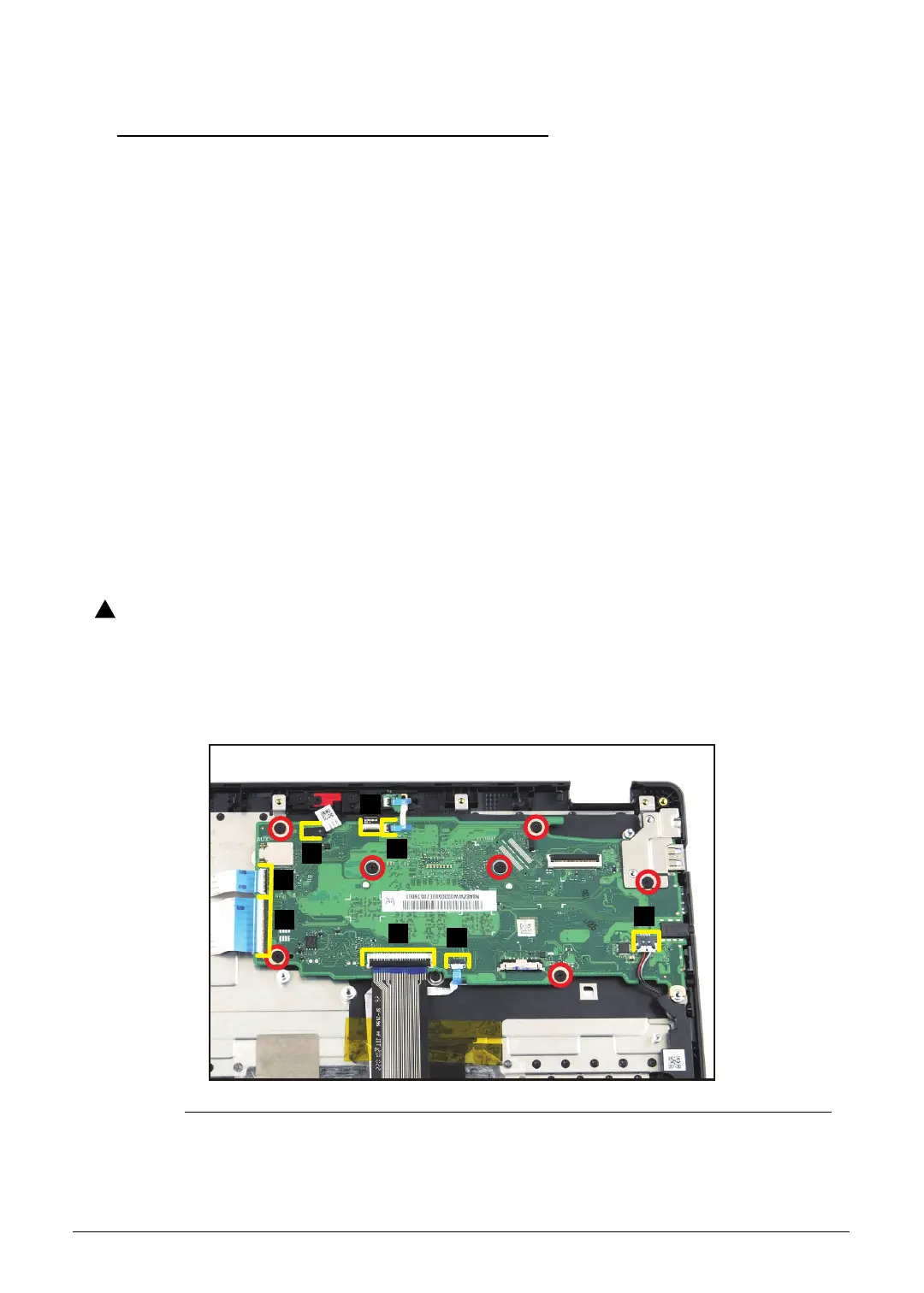
1. Release the latch and disconnect the LED cable from the mainboard connector (A)
(Figure 1-26).
2. Release the latch and disconnect the camera cable from the mainboard connector (B)
(Figure 1-26).
3. Disconnect the microphone cable from the mainboard connector (C) (Figure 1-26).
4. Release the latch and disconnect the 20-pin USB board FFC from the mainboard
connector (D) (Figure 1-26).
5. Release the latch and disconnect the 50-pin USB board FFC from the mainboard
connector (E) (Figure 1-26).
6. Release the latch and disconnect the keyboard FPC from the mainboard connector (F)
(Figure 1-26).
7. Release the latch and disconnect the touchpad FFC from the mainboard connector
(G) (Figure 1-26).
8. Disconnect the speaker cable from the mainboard connector (H) (Figure 1-26).
Make sure all cables, FFCs, and FPC are disconnected from the connectors on
the mainboard to avoid damage during removal.
9. Remove seven (7) screws securing the mainboard and I/O bracket in place
(Figure 1-26).
Figure 1-26. Mainboard Removal
 Loading...