Do you have a question about the Acer e-mill 3VSII and is the answer not in the manual?
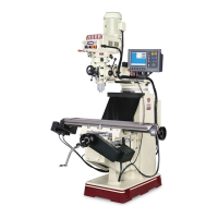
Details the operation of the vertical turret milling machine.
Lists the manufacturer and distributor contact details.
Covers general safety guidelines for operating the milling machine.
Specific safety guidelines for securing workpieces during operation.
Safety precautions specifically for maintenance tasks.
Safety measures to be followed during machine installation.
Details on proper electrical grounding for the machine.
Specifies the ideal environmental conditions for machine installation.
Broad safety advice applicable to various machine operations.
Essential checks to perform before powering on the machine.
Regular inspection tasks to ensure safe operation.
Steps for warming up the machine before use.
Tasks and checks needed before starting machine operations.
Safe practices and procedures during machine operation.
Information regarding the operational noise level of the machine.
Procedures for safely interrupting machine operations.
Steps to follow after finishing a machining job.
Identification and description of the machine's safety features.
Steps required before commencing maintenance operations.
Guidelines for carrying out maintenance safely and effectively.
Procedures for safely restarting the machine after maintenance.
Lists physical dimensions and technical specifications for various models.
Technical details pertaining to the milling head.
Identifies and describes key features and components of the machines.
Safe methods for lifting and moving the machine.
Guidelines for preparing a stable and level base for the machine.
Steps for leveling the machine and adjusting handles.
Instructions for safely connecting the machine to the power source.
Electrical circuit schematics for standard machine models.
Identification and description of controls on the main panel.
Diagram showing component placement within the electric cabinet.
A detailed list of electrical parts used in the machine.
Specific electrical circuit schematics for the 6VK model.
Explanation of the controls and indicators on the operation panel.
Specific explanation of the 6VK operation panel controls.
Layout of the electric cabinet for UL-certified models.
Component list related to UL-certified electrical diagrams.
UL-certified electrical schematics for models 3VS through 5VK.
UL-certified electrical schematics for the 6VK model.
Comprehensive list of electrical components with part numbers.
Updates or changes to the UL parts list.
Steps for accurately aligning the machine head.
General lubrication requirements for machine operation.
Specific lubrication diagram for the 3VK model.
Lubrication diagrams for 3VKH and 5VK models.
Lubrication diagram for the 6VK model.
Recommended frequency and quantity for lubrication tasks.
Safety information regarding the lubricant used in the machine.
Key safety guidelines for operating the milling machine.
Identifies machine parts with numbered diagrams for specific models.
Identifies machine parts with numbered diagrams for 5VK & 6VK models.
Instructions on using the drawbar for tool changes.
Function and use of the spindle brake mechanism.
Operation of the motor direction control switch.
How to select speed ranges using the Hi-Neutral-Lo lever.
Mechanism for engaging the machine's power feed.
Adjusting feed rates for the quill.
Control for reversing the feed direction.
Operating the manual feed handwheel.
Function and adjustment of the feed control lever.
Instructions on how to remove the quill feed handle.
Use of the quill stop knob for setting depth.
Setting depth precisely using the micrometer adjusting nut.
How to lock the quill in a stationary position.
Procedure for moving and securing the ram.
Securing machine components for increased rigidity.
Best practices and tips for efficient milling operations.
How to adjust the table's gibs for smooth movement.
Procedure for adjusting the saddle and knee gibs.
Steps for disassembling the table and saddle components.
Correcting and reducing play in the machine leadscrews.
Steps to safely remove the machine's motor.
Instructions for replacing the vari-drive V-belt.
Steps for replacing the machine's timing belt.
Procedure for replacing internal return springs.
A schedule outlining routine maintenance tasks.
Tables providing recommended cutting speeds for various materials.
Details required for ordering replacement parts.
Illustrated breakdown of the 3HP milling head assembly.
Itemized parts for the 3HP milling head.
Illustrated breakdown of the 3HP head top housing.
Itemized parts for the 3HP head top housing.
Illustrated breakdown of the 3HP head back gear.
Itemized parts for the 3HP head back gear.
Illustrated breakdown of the 5HP hand feed assembly.
Itemized parts for the 5HP hand feed assembly.
Illustrated breakdown of the 5HP spindle assembly.
Itemized parts for the 5HP spindle assembly.
Illustrated breakdown of the 5HP auto feed assembly.
Itemized parts for the 5HP auto feed assembly.
Illustrated breakdown of the 5HP E-mill head top housing.
Itemized parts for the 5HP E-mill head top housing.
Illustrated breakdown of the 5HP E-mill head back gear.
Itemized parts for the 5HP E-mill head back gear.
Illustrated breakdown of the 3VS & 3VSII basic machine.
Itemized parts for the 3VS & 3VSII basic machine.
Illustrated breakdown of the 3VK basic machine.
Itemized parts for the 3VK basic machine.
Illustrated breakdown of the 3VKH basic machine.
Itemized parts for the 3VKH basic machine.
Illustrated breakdown of the 5VK basic machine.
Itemized parts for the 5VK basic machine.
Illustrated breakdown of the 6VK basic machine.
Itemized parts for the 6VK basic machine.
Illustrated breakdown of leadscrew assemblies for 3VS-5VK models.
Itemized parts for leadscrew assemblies of 3VS-5VK models.
Illustrated breakdown of the 6VK leadscrew assembly.
Itemized parts for the 6VK leadscrew assembly.
Illustrated breakdown of the machine's electric cabinet.
Lists and diagrams safety accessories like chip pans and guards.
| Brand | Acer |
|---|---|
| Model | e-mill 3VSII |
| Category | Power Tool |
| Language | English |