- 48 -
2.) EEPROM:
We use 24C16 EEPROM to store monitor user data and user preset timings.
There are 16 user timing modes are automatically saved in it. Each timing mode is
allocated with 22 bytes of memory space for information such as Sync frequencies,
polarities… etc. PC can access the EEPROM data indirectly through the SDA and
SCL channels of DVI and D-sub (IIC communication). The digital and analog DDC
data are stored in two 24C02s EEPROM.
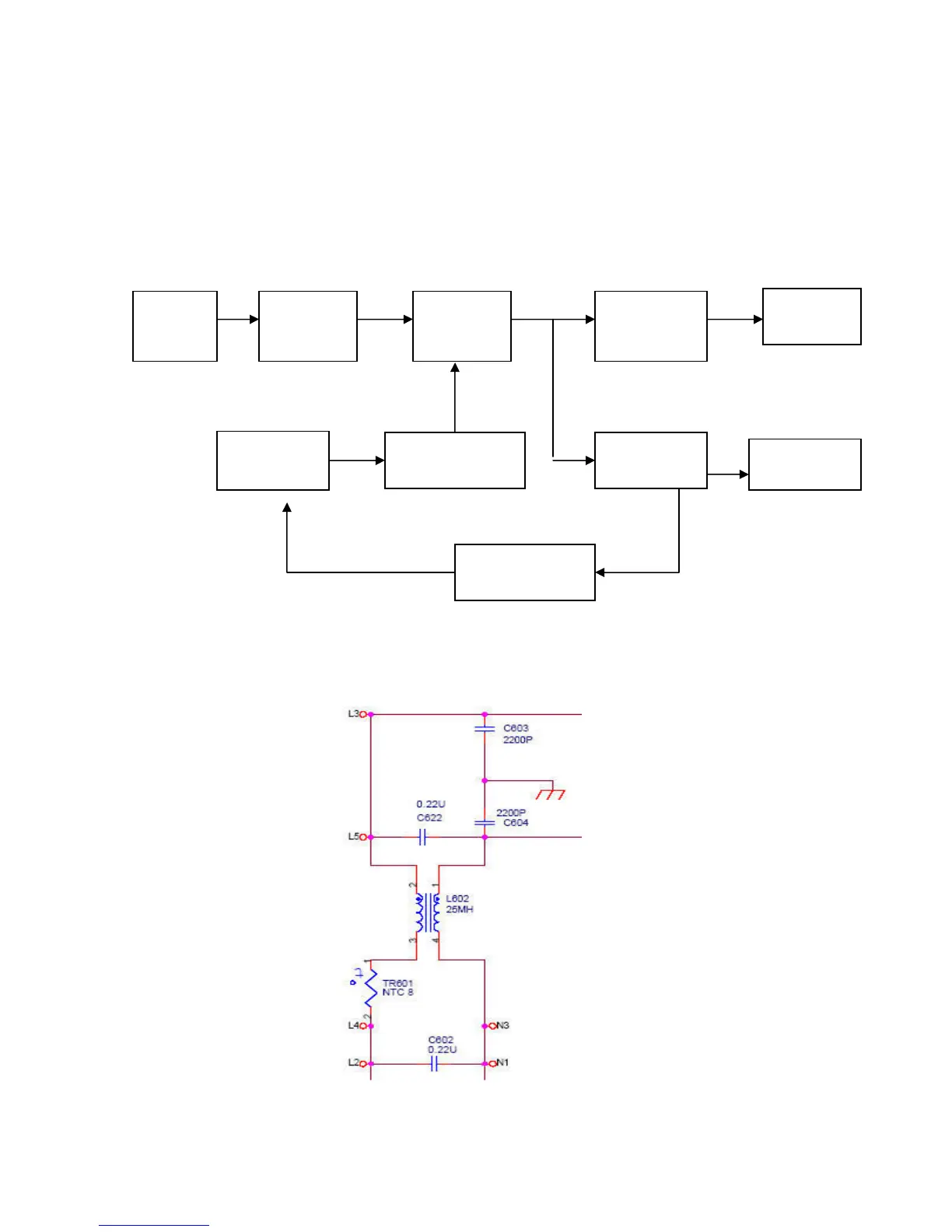
A-2.) Power board diagram:
Fig.1
#1 EMI Filter
This circuit (fig. 2) is designed to inhibit electrical and magnetic interference for meeting FCC,
VDE, VCCI standard requirements.
Fig. 2
Filter
and filter
power
and filter
controller
element
Isolation
circuit
and filter
 Loading...