What to do if my Acer Monitor has no display and the LED is amber?
R
Robert MartinezJul 26, 2025
If your Acer Monitor screen is black, and the LED is amber, make sure the sync signal from your computer is being outputted. Also, verify that the video cable is correctly connected. You may need to input the sync signal from the computer or try changing the cable. You can also proceed by checking the resolution change IC movement.
Y
yandersonAug 4, 2025
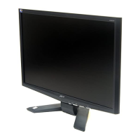
Why is there nothing displaying on my Acer X203 (screen is black, color of LED is blue)?
A
Antonio CastilloAug 4, 2025
If your Acer Monitor displays nothing on the screen, but the LED is blue, try the following:
1) Change the pattern of the video signal output on the host.
2) Reconnect the video cable.
3) Change the video cable. You can also refer to the section on checking the backlight unit or proceed to the 'Abnormal screen detection' section.
M
Monica HarrisAug 15, 2025
How to check the DC/DC converter circuit on Acer X203?
G
George MasonAug 15, 2025
To check the DC/DC converter circuit in your Acer Monitor, verify that 5V is output from P301 pin5 and pin6, and that 5V is input to I302 pin3. Also, confirm that 3.3V is output and input to Q305 pin1, and that 1.8V is output.