EasyManua.ls Logo

Acer X223 User Manual

Acer X223
41 pages
To Next Page IconTo Next Page
Page #1 background imageLoading...
Page #1 background image
Table of Contents
Important Safety Notice------------------------------------------------------------------------------------- 01
01. Product Specification--------------------------------------------------------------------------------- 02
02. OSD Menu-----------------------------------------------------------------------------------------------08
03. Exploded Diagram
05.
AppendixI:User’s Manual
Appendix II: Quick Setup Guide
------------------------------------------------------------------------------------- 10
Troubleshooting----------------------------------------------------------------------------------------20
06. Schematics and Layouts------------------------------------------------------------------------------ 30
04. Assembly and Disassembly Procedures-----------------------------------------------------------12
Appendix III : Spare Parts Llist
Safety Notice
Any person attempting to service this chassis must familarize with the chassis and be aware of the
necessary safety precautions to be used when serving electronic equipment
containing high voltage.
Published by LITE-ON Service Printed in Taiwan © All rights reserved Subject to modification
23th-Jul-2007
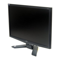
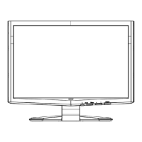
Model ID: R22ANUW-M1
Service
ACER
ACER_LCD_X223W_SM072301V1
Service Manual

Questions and Answers:

Acer X223 Specifications

General IconGeneral
Screen Size22 inches
Resolution1680 x 1050
Panel TypeTN
Brightness300 cd/m²
Response Time5 ms
Aspect Ratio16:10
Viewing Angle (H)170°
Viewing Angle (V)160°
ConnectivityVGA, DVI

Summary

Important Safety Notice

Product Announcement

Details product certification for RoHS and Lead-Free production, and vendor liability.

Qualified Repairability

Emphasizes the importance of proper service and training for safe product operation.

Safety Notices and Precautions

Lists critical safety instructions to prevent electrical shock and product damage during servicing.

Product Specification

SCOPE

Defines design and performance requirements for the 20/22W inch flat panel monitor.

GENERAL REQUIREMENTS

Outlines test conditions and equipment for evaluating monitor performance.

ELECTRICAL

Describes the monitor's electrical subsystems and specifications, including block diagrams.

Video Signal Amplitudes

Details the amplitudes of Red, Green, and Blue video input signals.

Video Signal Termination Impedance

Specifies the resistive termination impedance for analog video signals.

Synchronization (Sync) Signals

Explains Horizontal and Vertical Sync signals used for display synchronization.

Sync Signal Levels

Defines the voltage levels required for TTL logic families for sync signals.

Abnormal Signal Immunity

Describes the monitor's resilience to various input signal anomalies.

User Controls and Indicators

Details the front panel controls, power indicator LED, and OSD menu interaction.

OSD Adjustment

Lists adjustable parameters within the On-Screen Display menu for picture settings.

Monitor Modes and Timing Capability

Explains the monitor's ability to synchronize with various frequencies and its pre-set display modes.

Mode Recognition Pull-in

Covers how the monitor recognizes preset modes based on input signal characteristics.

User Display Modes

Details the provision for storing and recalling up to 9 user-defined display modes.

Video Stretching

Discusses the monitor's ability to automatically expand video signals to fill the screen.

Power Supply Requirements

Specifies the requirements for the external AC to DC converter power supply.

Display Communications Channel

Details the VESA DDC2Bi compliant communication channel for display information.

Firmware Update Function

Explains the process for updating monitor firmware via the D-Sub connector.

PANEL ELECTRICAL

Outlines general requirements for the WSXGA resolution TFT-LCD panel.

Backlight Requirements

Specifies requirements for the backlight assembly, including lamp life and startup time.

Defect Terminology

Provides descriptive terms for classifying defects found on the LCD panel.

LCD Inspection Criteria

Details the procedure for LCD panel inspection and allowable defect limits.

Optical Characteristics

Refers to optical specifications determined by the LCD supplier.

OSD Menu

MAIN OSD MENU

Describes the main OSD menu structure and control functions for monitor settings.

Hot-Key Menu

Explains the functionality of hot-keys for quick adjustments like volume.

OSD Message

Lists and describes various messages that can be displayed within the OSD interface.

Scenario Mode Operation

Explains how to select and operate different scenario modes and the DCC/CI switch.

Exploded Diagram

Packing Exploded Diagram

Illustrates the exploded view of the monitor packaging contents and accessories.

Product Exploded Diagram

Provides a detailed exploded view of the monitor's internal components and assembly parts.

Assembly and Disassembly Procedures

Assembly Procedures

Step-by-step instructions for assembling the monitor unit and its components.

Disassembly Procedures

Step-by-step instructions for safely disassembling the monitor for repair or maintenance.

Troubleshooting

No display of screen (Amber LED)

Guides through diagnosing 'No display' issues when the power LED is amber.

Nothing display on screen (Blue LED)

Continues troubleshooting for black screen issues when the power LED is blue, checking backlight and menu.

Checking the back light unit

Provides steps to diagnose issues related to the monitor's backlight unit.

Abnormal screen for VGA

Details troubleshooting for abnormal screen display specifically for VGA input signals.

Abnormal OSM display adjust problem

Covers troubleshooting issues related to OSD display adjustments and input signal levels.

Abnormal plug and play operation for VGA

Guides on resolving plug and play operation failures and video cable connection issues.

Checking the interface circuit of sync signal

Details procedures for checking sync signal interface circuits and resolution change IC movement.

Checking the resolution change IC movement

Focuses on verifying power supplies and SPI signals for resolution change ICs.

Checking the DC/DC converter circuit

Provides steps to diagnose issues within the DC/DC converter circuits for various voltage outputs.

Schematics and Layouts

Block Diagram

Presents the overall system block diagram illustrating component interconnections.

Power Board Schematic

Detailed schematic of the monitor's power board components and connections.

Interface Board Schematics

Schematics for interface board sections: VGA, DVI, Scaler, Key/Panel.

Interface Board Power Schematic

Schematic detailing the power-related circuits on the interface board.

Interface Board VGA Schematic

Schematic detailing the VGA and DDC interface circuits on the interface board.

Interface Board Scaler Schematic

Schematic detailing the scaler IC and associated components on the interface board.

Interface Board Key & Panel Schematic

Schematic detailing the key input and panel interface connections on the interface board.

Function Key Board Schematic

Schematic diagram for the function key control board and its connections.

Power Board Layout

Illustrates the physical component placement on the top and bottom of the power board.

Interface Board Layout

Illustrates the physical component placement on the interface board.

Function Key Board Layout

Illustrates the physical component placement on the function key board.

Related product manuals