Chapter3 Installation / 21
ISA SLOT1
FAN1
down :
up
K/B
:Mouse
USB
COM1
COM2
Printer
MIDI/
GAME/
AUDIO
FAN2
FAN 3
JP1
IDE
FDC
SOCKET
J3
LAN
82443BX
JP5
1
IR
J2
12
PCI1PCI2PCI3PCI5 PCI4
ISA SOLT
AGP1
AGP SOLT
J6
1
JP7
1
1
JP6
DIMM
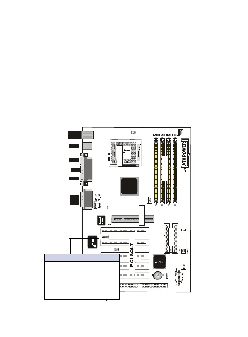
9. IrDA / Fast IR-Compliant infrared module connector - IR(J1)
This connector supports the optional wireless transmitting and
receiving infrared module. This module mounts to a small open-
ing on system cases that support this feature. You must also
configure the setting through UART2 Use Infrared” in Chipset
Feature Setup to select whether UART2 is directed for use with
COM2 or IrDA. Use the five pins as shown on the Back View
and connect a ribbon cable from the module to the motherboard
according to the pin definitions.
Pin Description
1 VCC
2 Option
3 IRRX2
4 Ground
5 IRTX2
IrDA/Fast IR Connector