28
Component Testing Procedures
!
WARNING
To avoid risk of electrical shock, personal injury or death, disconnect power to oven and discharge capacitor
before servicing, unless testing requires power.
Illustration Component Test Results
1
2
4
7
6
5
8
Terminal 1
230 V
Terminal 2
Common
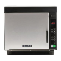
Transformer
# 4
1
2
5
# 6
7
8
1.0 F
-300 MA
-300 MA
1.0 F
Discharge Capacitors
Remove all wires from terminals.
Measure resistance from:
Terminal 1 to 2................................................
Terminal 5 to 6................................................
Terminal 7 to 8................................................
Terminal 4 to Ground screw on transformer...
Terminal 4 to any other terminal.....................
Gray Pink
1 2
1.0 .
Less than 1 .
Less than 1 .
30 .
Infinite resistance. If not, replace
transformer.
Primary /
Logic
Secondary
Monitor
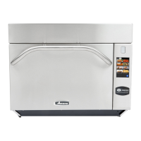
Interlock switch
assembly
Disconnect wires to switch.
With door open measure resistance from:
Terminal C to NC Monitor..........................
Terminal C to NO Primary / Logic..............
Terminal C to NO Secondary ....................
With door closed measure resistance from:
Terminal C to NC Monitor..........................
Terminal C to NO Primary / Logic..............
Terminal C to NO Secondary ....................
Door Closed
Primary / Logic
C
NC
NO
C
C
NO
Secondary
Monitor
Continuity.
Infinite.
Infinite.
Infinite.
Continuity.
Continuity.
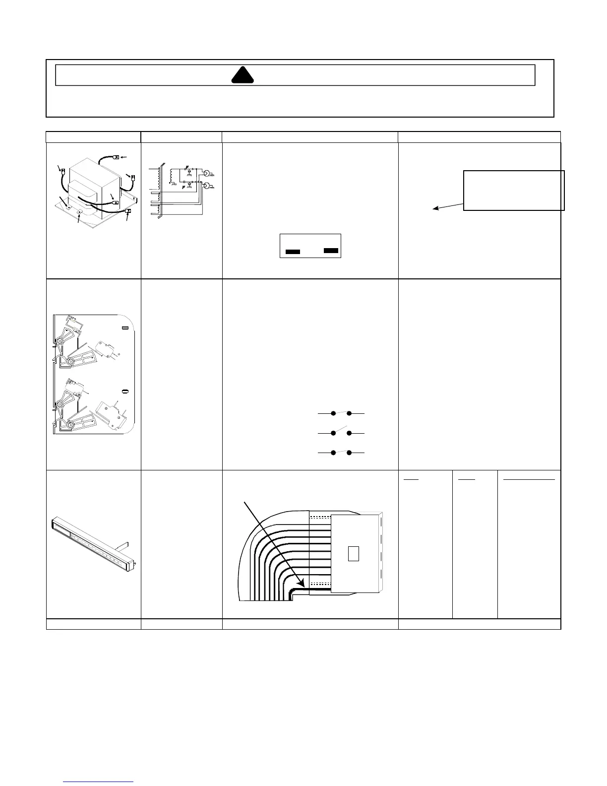
Touch Panel
Assembly
Continuity is indicated as 100 and below.
Pin 1: Ground.
Pad
1
2
3
4
5
6
7
8
9
0
Start
Stop/Reset
Power Level
X 2
Time Entry
Pins
8 & 10
7 & 10
6 & 10
5 & 10
4 & 10
3 & 10
8 & 9
7 & 9
6 & 9
5 & 9
4 & 9
4 & 8
5 & 8
6 & 8
7 & 8
Measurement
Continuity
Continuity
Continuity
Continuity
Continuity
Continuity
Continuity
Continuity
Continuity
Continuity
Continuity
Continuity
Continuity
Continuity
Continuity
Wire Harness Test continuity of wires ................................... Continuity.
!"#$%&'&(%)%*&+,&-*,./0+&
1%02& 2%%+&),*&#*,#%*&32"&
*%454+!60%&7!$/%8