29
Component Testing Procedures
!
WARNING
To avoid risk of electrical shock, personal injury or death, disconnect power to oven and discharge capacitor
before servicing, unless testing requires power.
Illustration Component Test Results
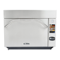
Control board
P2
1
10
P1
1
10
P1 connector used
for touch panel
ribbon
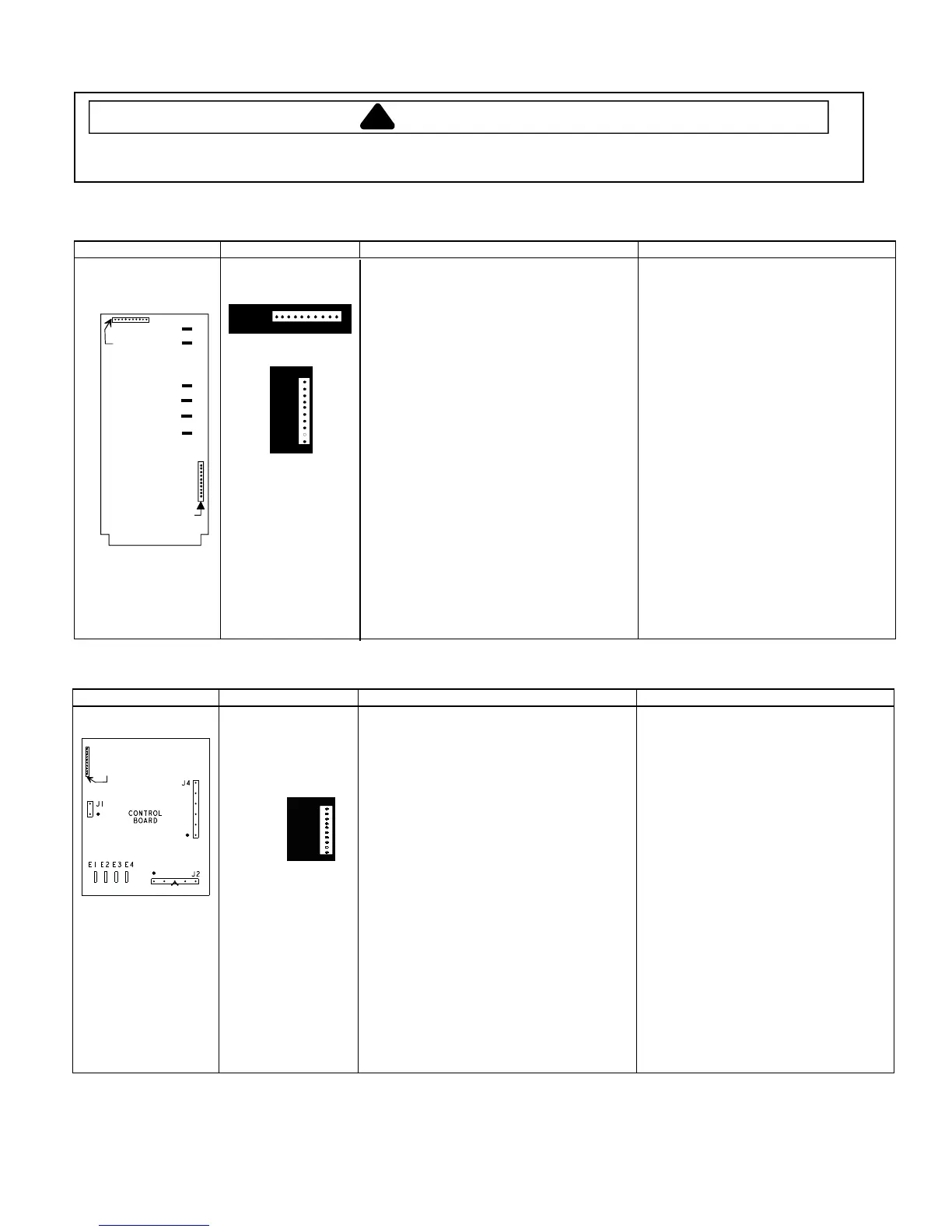
Illustration Component Test Results
CONTROL
BOARD
J2
J1
J4
E1 E2 E3 E4
Pin #1
P1
Control board
P1
1
10
P1 connector used
for touch panel
ribbon
Line voltage to control board
E1 (RD) —L2 (BU) ...................................
Output drive voltage to triac
Triac terminals.............................................
Gate (BR) —T1 (BK) .................................
230 VAC line voltage
Fan relay (controls blower motor, antenna
motor(s), and oven light)
Control board...............................................
Terminals L2 (BU) —J2-7 (OR).................
Control board...............................................
Terminals E1 (RD) —E4 (PK) ...................
Line voltage (All Conditions)
0 VAC (Idle and Standby)
0.9 VAC (Cook)
Line voltage (Idle)
0 VAC (Standby and Cook)
Line voltage (Idle)
0 volts (Standby and Cook)
Invensy Control Board
CPI Control Board
Pin #1
Pin #1
P1
P2
A
B
C
J
F
K
Line voltage to control board
P2 connector
Pin 1—Pin 3..............................................
Output drive voltage to triac
Triac terminals............................................
Gate—T1..................................................
Fan relay (controls blower motor, antenna
motor(s), and oven light)
Control board ..............................................
Terminals C—J.........................................
Cook relay
Control board ..............................................
Terminals F—K.........................................
Line voltage (All Conditions).
0 VAC (Idle and Standby).
0.9 VAC (Cook).
Line voltage (Idle).
0 VAC (Standby and Cook).
Line voltage (Idle).
0 volts (Standby and Cook).