Illustration Component Test Results
With Line Voltage Applied:
J1-1 (WH) to J1-3 (BK) …………………
J2-1 (RD) to J2-5,6,&7…………………
Line Voltage AC
Approximately 24VDC
DISCHARGE CAPACITORS!
Wires Removed:
COM to 208 or 230……………...……..
5 to 6………………………………...………..
4 to Chassis Ground……………………
Resistance:
<2Ω (Open to Ground)
<1Ω (Open to Ground)
Approximately 62.5Ω ± 5%
DISCHARGE CAPACITORS!
Diode Removed from Capacitor
OPEN (∞) when measured in one
direction, 50KΩ or more in the
other direction. NOTE: Meter must
have >6VDC Battery to effectively
measure
Wires Removed:
BK to RD 3/16" Terminals…………….
BK (1/4") to YL Terminal……………….
BK to BU Terminals………………………
Resistance:
Approximately 550Ω (Solenoid)
Normally Closed - Continutity
Normally Open - OPEN (∞)
Relay, Power
(208/230VAC)
Wires Removed:
0 to 1……………………………………..…...
2 to 4 ………………………………………....
6 to 8 ………………………………………….
Resistance:
Approximately 550Ω (Solenoid)
Normally OPEN (∞)
Normally OPEN (∞)
Snubber (Transformer &
Relay)
Wires Removed:
Terminal to Terminal …………………
Use Test Plug By Main Board:
BU to RD Door Open …..……………
BU to RD Door Closed ………………..
Resistance:
Continuity
OPEN (∞)
NOTE: When opening door, the
Primary Switch should ALWAYS
activate first.
Switches, Monitor &
Secondary
Use Test Plug with Door Closed:
VT to BU (Monitor Switch) …………
VT to OR (Secondary Switch) …….
Resistance with Door Closed:
OPEN (∞)
Continuity
NOTE: When opening door, the
Primary Switch should ALWAYS
activate first.
Thermal Cutout (TCO),
Cavity
Wires Removed (one set is used):
11 to 12………………………...……….....
21 to 22 ………………………………...….
31 to 32……………….……………….…...
With Mechanical Reset Button "in":
Continuity at Temperatures
Between 608°F (320C) and 32°F (0C)
Thermal Cutout (TCO),
Magnetron
Wires Removed:
Terminal to Terminal…………………..
Opens at 300°F (320C). Resets at
257°F (125C)
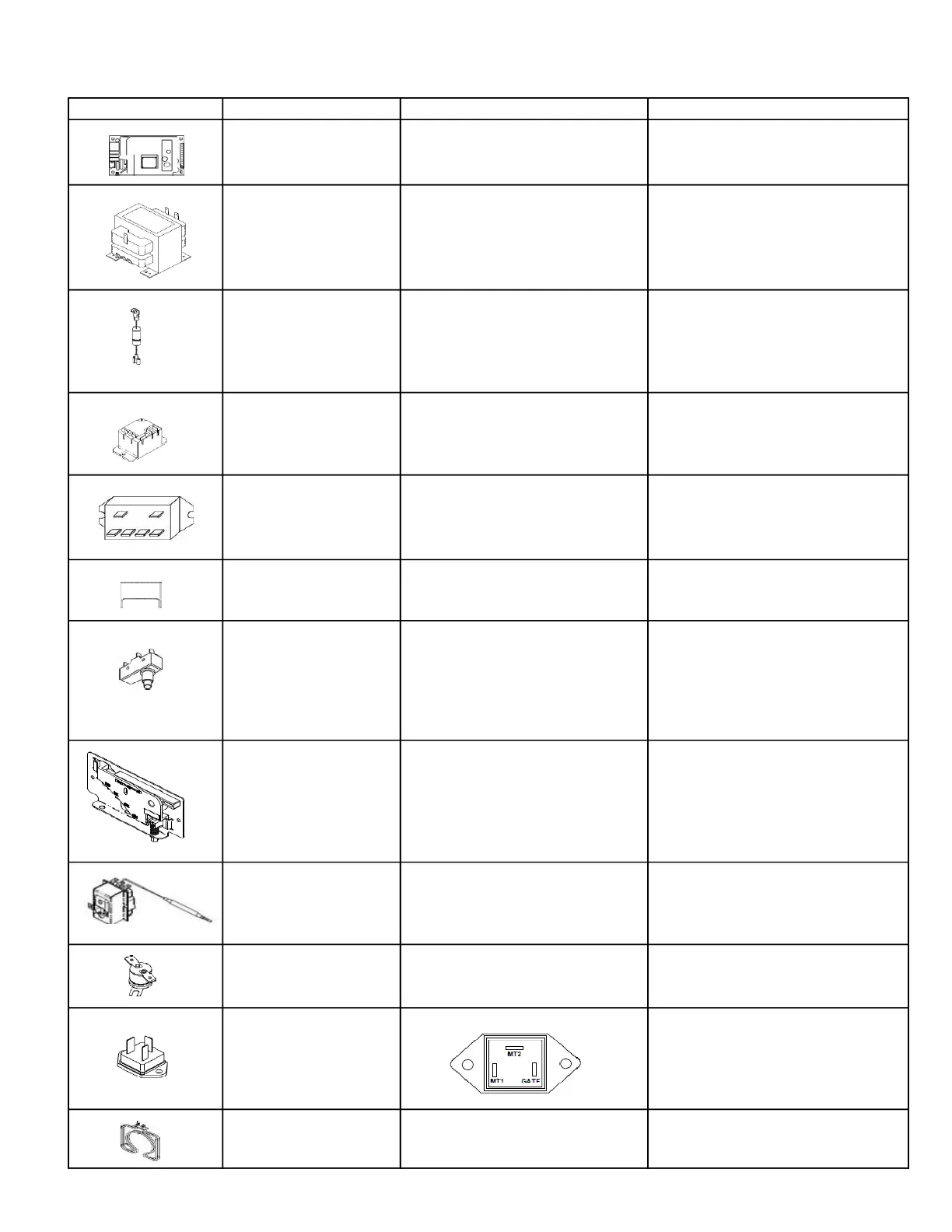
Triac (Fan, Heater, &
Transformer)
Wires Removed:
MT1 to Gate Approximately 50Ω
MT1 to MT2 - OPEN (∞)
MT2 to Gate - OPEN
All Terminals OPEN (∞) to Ground
Wires Removed:
Terminal to Terminal…………………..
Resistance:
Approximately 15Ω
COMPONENT TESTING PROCEDURES
 Loading...