Illustration Component Test Results
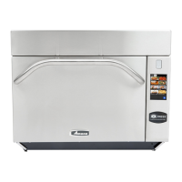
230 to 0 (Com)……………………….....
208 to 0 ………………………………...….
120 to 0 (not used)……………….…...
Approximately:
38 Ω
35 Ω
25 Ω
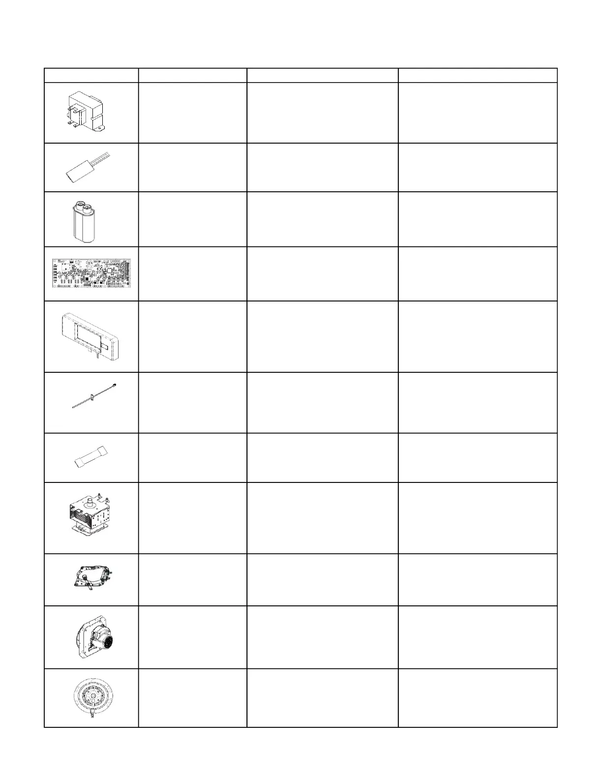
Capacitor, Cooling Fan
Motor
Wire to Wire 1.5µf ± 5% 400V 50/60hz
Capacitor, High Voltage Terminal to Terminal .88µf ± 3% 2100V 50/60hz
Control Board, Main See Service Test Mode Section
Control Board, Touch
Screen Display
See Service Test Mode Section
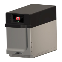
Convection RTD
(Resistive Thermal
Device) aka Temp
Sensor
Temperature:
70°F (23.9C)………………………………..
350°F (176.7)……………………………...
Approximately:
1100Ω
1650Ω
F1 - BLN 250V 30A………………………
F3 & F4 250V 12A……………………….
DISCHARGE CAPACITORS!
Wires Removed:
Terminal to Terminal…………………..
Both Terminals to Chassis…………..
Wires Removed:
Terminal to Terminal…………………..
Approximately:
12,000Ω (12KΩ)
With Line Voltage Applied & ST2
Connector Unplugged:
ST1-1 to ST1-2……………………………
Motor not running with line voltage
present indicates a failed motor
assembly.
Wires Removed:
BU to BRN………………………………….…
BU to BK……………………………….……..
BK to BRN…………………………….………
Approximately:
200Ω
685Ω
900Ω
COMPONENT TESTING PROCEDURES