Component Testing Procedures
!
WARNI NG
To avoid risk of electrical shock, personal injury or death; disconnect power to oven and discharge capacitor
before servicing, unless testing requires power.
January 2012 16500030
©2012 ACP, Inc.
3
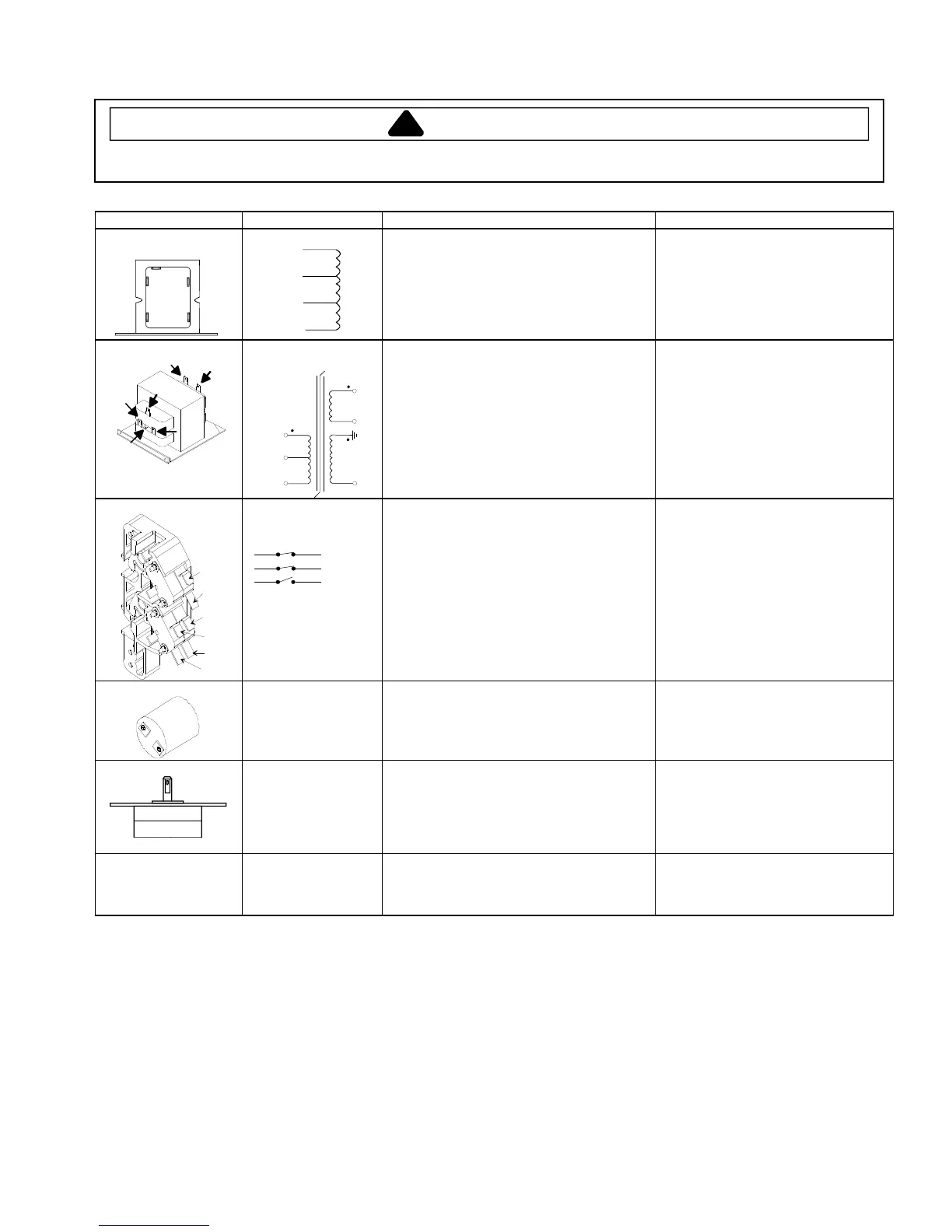
Illustration Component Test Results
208 V
COM
0 V
230 V
120 V
Auto Transformer
230
208
120
0
Discharge Capacitors
Remove all wires from terminals.
Measure resistance from:
230 V to 0 V ..............................................
208 V to 0 V ..............................................
120 V to 0 V ..............................................
Approximately 38 Ω
Approximately 37 Ω
Approximately 25 Ω
4
COM
230
208
5
6
Transformer
4
COM
208 VAC
230 VAC
5
6
Discharge Capacitor
Remove all wires from terminals.
Measure resistance from:
230 to COM ..............................................
208 to COM ..............................................
230 to Ground...........................................
208 to Ground...........................................
Terminal 5 to 6 .........................................
Terminal 4 to Ground ...............................
Less than 1 Ω
Less than 1 Ω
Infinite
Infinite
Less than 1 Ω
Approximately 59 Ω
7
8
2
3
5
Interlock switch
Door Closed
2
4
7
3
5
8
Primary
Secondary
Monitor
Disconnect wires to switch.
With door open measure resistance from:
Terminal 2 to 3 .........................................
Terminal 4 to 5 .........................................
Terminal 7 to 8 .........................................
With door closed measure resistance from:
Terminal 2 to 3 .........................................
Terminal 4 to 5 .........................................
Terminal 7 to 8 .........................................
Infinite
Infinite
Indicates continuity
Indicates continuity
Indicates continuity
Infinite
Lamp receptacle
(some models)
Test continuity of receptacle terminals. Indicates continuity if bulb is good
and screwed in.
Antenna motor Remove all wires from terminals.
Measure resistance from:
Terminal to terminal .....................................
Approximately 12K Ω
Refer to Parts Manual
for proper power cord
part number.
Power cord Measure resistance of wires. Continuity should be indicated on
each wire.
Verify polarity and grounding.