Component Testing Procedures
!
WARNI NG
To avoid risk of electrical shock, personal injury or death; disconnect power to oven and discharge capacitor
before servicing, unless testing requires power.
January 2012 16500030
©2012 ACP, Inc.
5
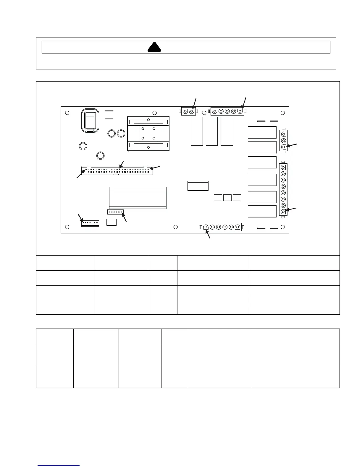
H.V. board
Pin 1
Pin 1
Pin 1
Pin 1
Pin 1
Pin 1
Pin 1
Pin 1
Pin 50
Pin 28
J1
J2
J5
J8
J6
J7
J3
J4
E4 E5
E7 E6
E1
E2
E3
Function Test Set-Up Meter
Setting
Probe Placement Results
Input to H.V. board At H.V. board Volts J1 pin 1 (Brown wire)
& J1 pin 2 (White wire)
Line voltage
Output to display
board
Disconnect
J5 connector,
blower runs
continuously
Volts J5 pin 28 &
J5 pin 50
- 24 VDC
NOTE: For the following test, place oven in Service Test Mode (see page 11).
Relay Function Test Set-Up Meter
Setting
Probe Placement Results
K1 at
230 VAC
line voltage
Blower motor
Antenna motor
Cavity light
Disconnect
J2 connector
Ohms J1 pin 1 (Brown wire)
& J2 pin 4
Test mode 5 off − no continuity
Test mode 5 on − < 1 Ω
K2 at
208 VAC
line voltage
Blower motor
Antenna motor
Cavity light
Disconnect
J2 connector
Ohms J1 pin 1 (Brown wire)
& J2 pin 3
Test mode 5 off − no continuity
Test mode 5 on − < 1 Ω