Component Testing Procedures
!
WARNING
To avoid risk of electrical shock, personal injury or death; disconnect power to oven and discharge capacitor
before servicing, unless testing requires power.
August 2012 16500040
©2012 ACP Inc.
3
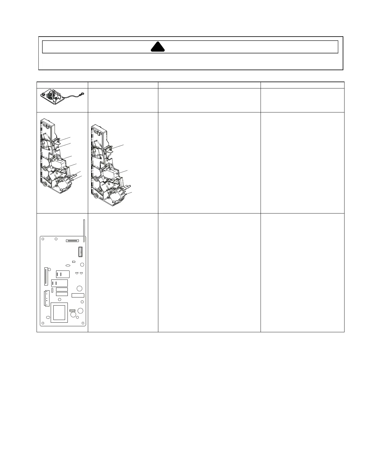
Illustration Component Testing Results
Fuse block / Filter assembly Power In terminals ......................................
Power Out terminals ...................................
120 VAC
120 VAC
If no power in, check power outlet
If no power out, check fuses
Interlock switch assembly
(Mechanical)
PRIMARY
INTERLOCK SWITCH
MONITOR
INTERLOCK SWITCH
SECONDARY
INTERLOCK SWITCH
Disconnect wires to switch.
With door open measure resistance from:
Monitor – Terminals 3 - 4 .................
Primary – Terminals 1 - 2 .................
Secondary – Terminals 5 - 6 ............
With door closed measure resistance
from:
Monitor – Terminals 3 - 4 .................
Primary – Terminals 1 - 2 .................
Secondary – Terminals 5 - 6 ............
After verifying or replacing the module,
re-connect wires to switch and check
operation of monitor circuit before
operating the oven.
Indicates continuity
Infinite
Ω
Infinite
Ω
Infinite
Ω
Indicates continuity
Indicates continuity
Relay 1
Relay 2
(CN1)
1 3 4 6 7
(CN3)
Dial Electronic control
1. (CN1 connector) Measure voltage at
BN (1) and BL (3) terminal leads ....
2. (Relay 1) Measure voltage across
BL and WH terminal leads ..............
3. (Relay 2) Measure voltage across
BL and WH terminal leads .................
Approximately 120 VAC
120 VAC OFF position (Door
Closed)
0 volts Cook mode (Door Closed)
120 VAC OFF position (Fan/Light
Off)
0 volts (Fan/Light ON)