N/O
Comm
N/C
0 1 2 3 4 5 6 7 8 9
B AT C H:
P R ODUC T:
S E R IAL NUMB E R:
01X X-1
AC T5 R E V1.0
00X XX X
Note
:
SCHRACK
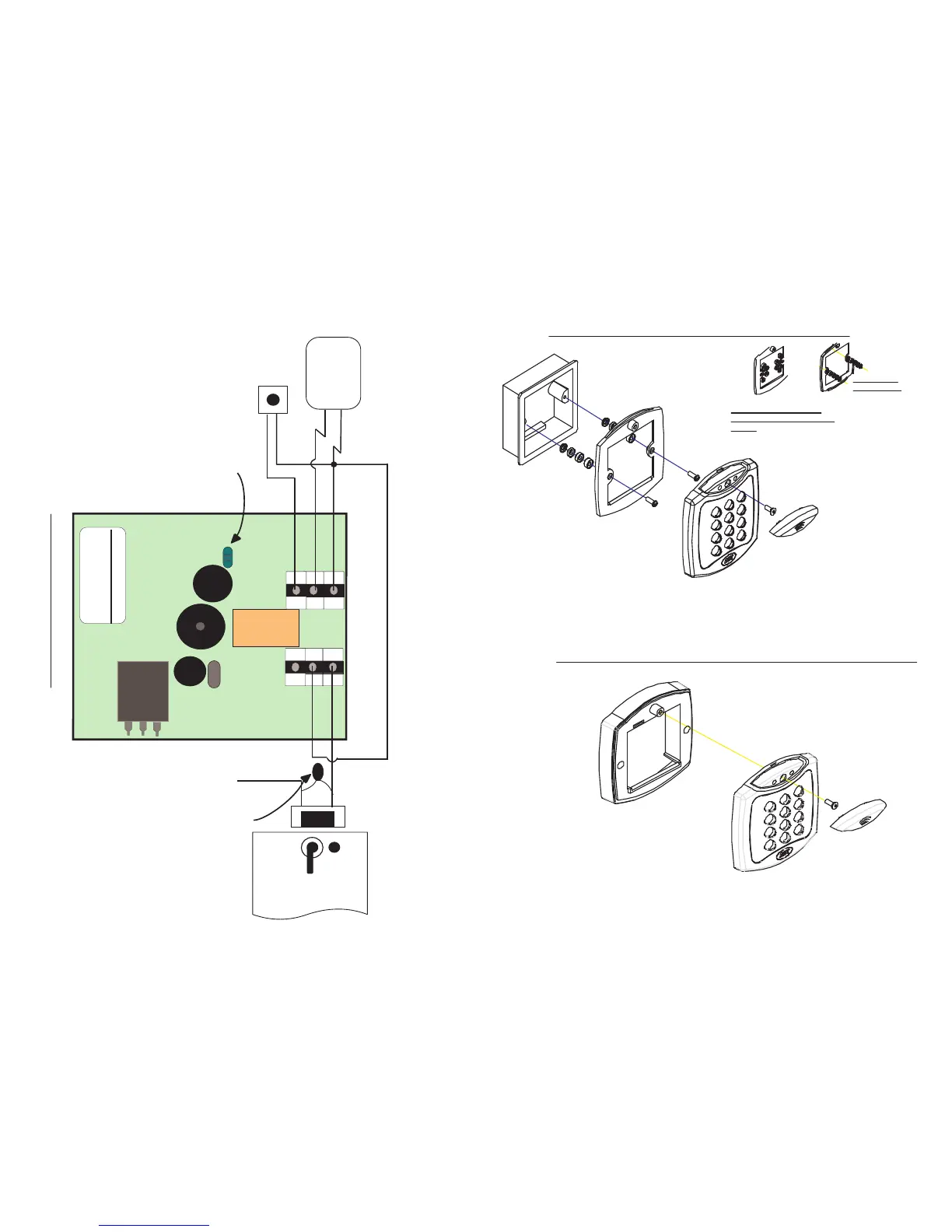
12V = DC
5A/250V ~AC
The ACT 5 may be powered
from 12 or 24V A C or DC.
Door R elease
B utton
Power
Supply Unit
T his illustr ation shows wir ing
for normally de-ener gised
locks. I f normally ener gised
locks ar e r equir ed, use the
N/C r elay contacts.
Important!
Always Place V aristor
Across L ock T erminals
+12V
0V
12-24V
AC/DC
Push B utton
0V
LK1
Power up without link if
Programming code has been lost
Security screw supplied with
the unit.
Place the Reader / Keypad onto the surface mount
collar and clip down into place.Use the security
screw supplied to attach the unit to the surfce mount
collar.
Mounting instructions for flush mount unit
View showing mounting plate
before spacers are broken away by
installer.
Mounting plate is attached to the pattress
box using the screws supplied, ENSURE
the corect spacers have been used to
bridge the gap between the mounting
plate and the fixing wings of the pattress
box to avoid the mounting plate being
distorted.
Standard pattress
box.
Spacers break
away from main
component when
required by
installer for use.
SCREWS
Note:
Determine the distance between the pattre
and the mounting plate, using the spacers
are labeled 1mm to 4mm. This allows the
installer to make the required spacer leng
10mm by stacking each spacer together.
Place the cap onto
the unit and push
firmly into place.
View showing
spacers stacking
Mounting instructions for surface mount unit
Place the Reader / Keypad onto the
surface mount collar and clip down into
place.Use the security screw supplied to
attach the unit to the surfce mount collar.
Fig 3
The surface mount collar is
mounted on the wall using
the fixing kit supplied in
the box.
Security screw supplied with
the unit.
Place the cap onto
the unit and push
firmly into place.
ACT5 Wiring Diagram
Fig 1
 Loading...