Hardware Manual
17
To connect output devices (DO), map the pins to one of the pin combinations below:
Connect the wires of the first output device to 12V
(Pin 2) and DO1 (Pin 4).
Connect the wires of the second output device to 12V
(Pin 6) and DO2 (Pin 8).
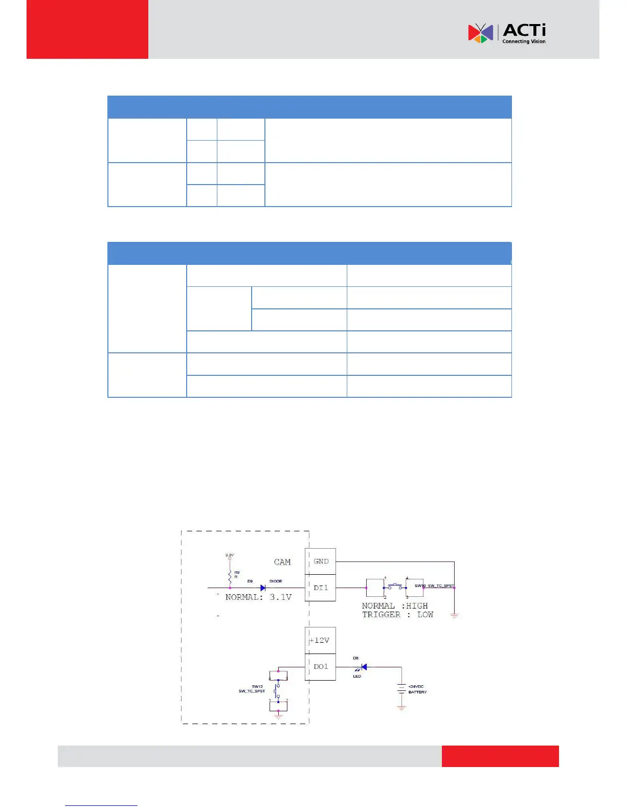
The table below shows the DI/DO connection specifications:
TTL - compatible logic levels
Logic level 1: 3.1V ~ 30V
Transistor (Open Collector)
Typical Connection
Based on these specifications, if the DI device has a voltage of 0V ~ 30V or the DO device has a
voltage of < 24V (<50mA), then the camera can supply internal power to these devices and there
is no need to connect the DI/DO device to an external power source.
In this case, wire connection to Pins 1 to 4. Use the GND and DI1 pins to connect a DI device and
use the 12V and DO1 pins to connect a DO device. See wiring scheme below: