Hardware Manual
23
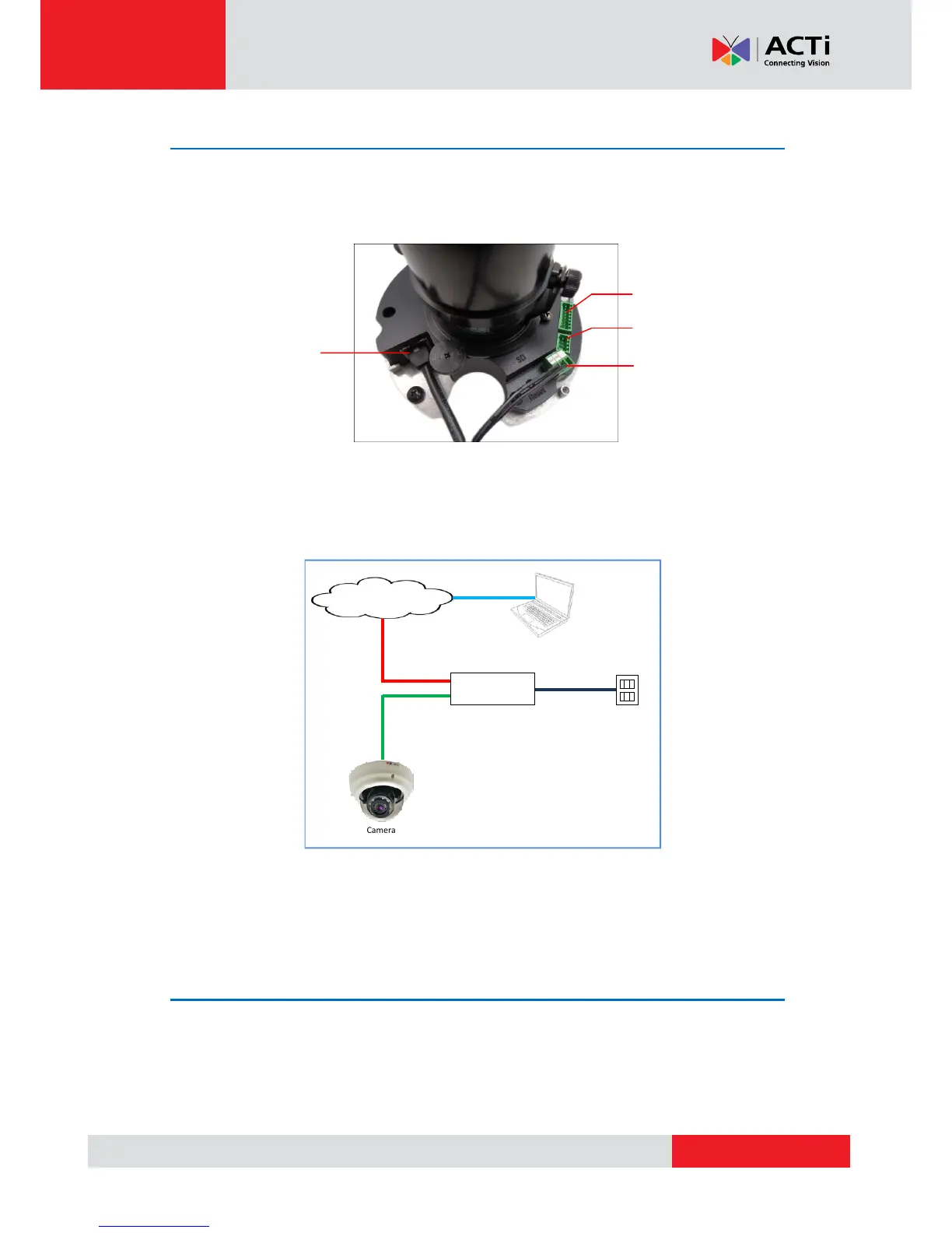
Step 4: Connect the Cable(s)
1. Connect the network cable to the Ethernet port of the camera.
If necessary, connect other cable connectors (optional), like audio input/output, DC 12V
power, and DI/DO to the corresponding connectors on the camera.
2. Connect the other end of the network cable to a switch or injector. Then, connect the switch
or injector to a network or PC and a power source. See Power-over-Ethernet (PoE)
connection example below.
In case of using a non-PoE switch, power up the camera using a power adapter (not supplied).
As needed, power up the other connected devices.
Step 5: Access the Camera Live View
See Accessing the Camera on page 30 for more information on how to access the Live View of
the camera.