KCM-5211 Hardware User’s Manual
8
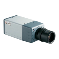
Physical description
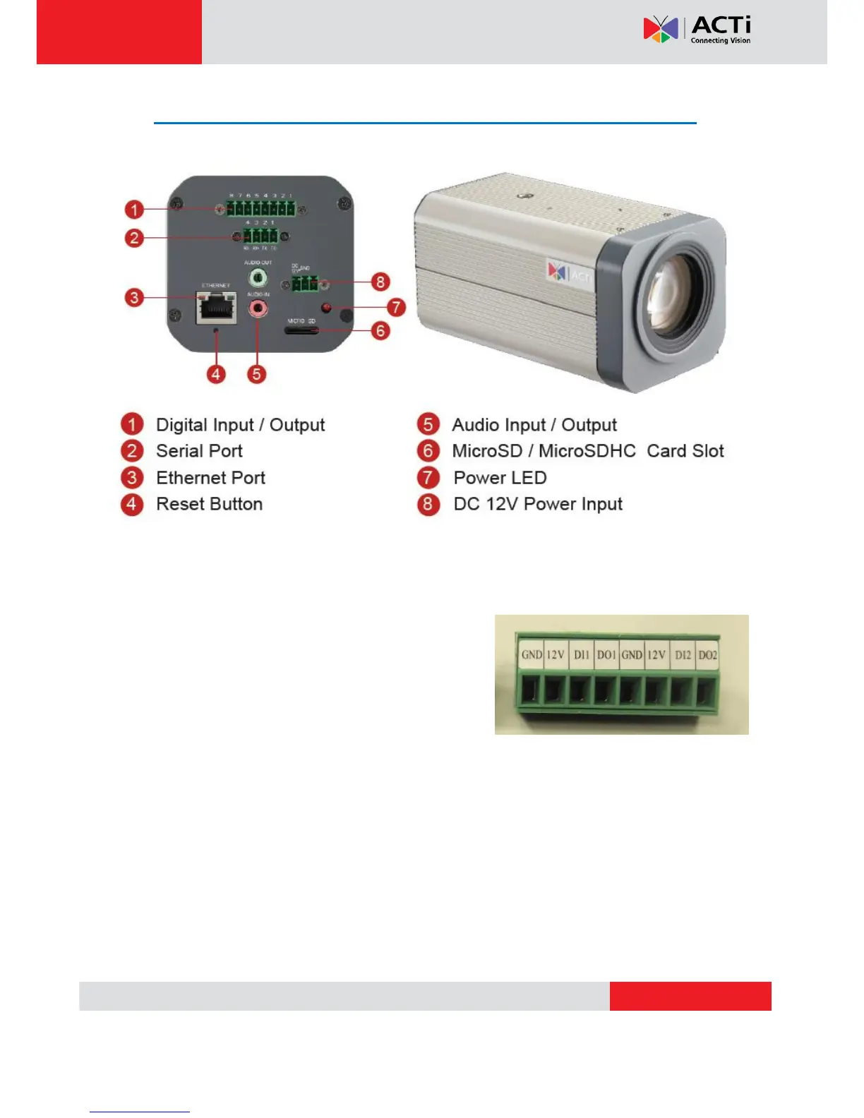
1) Digital Input / Output
Used in applications like motion detection, event triggering, time lapse recording, alarm
notifications, etc., the I/O terminal connector provides the interface to:
• 2 Transistor Outputs - For connecting external
devices such as relays and LEDs. Connected devices
can be activated by Output buttons on the Live View
page or through video management software. Connect
DO1 and DO2 to their closest 12V pin to activate.
• 2 Digital Inputs - An alarm input for connecting devices that can toggle between an open
and closed circuit, for example: PIRs, door/window contacts, glass break detectors, etc. The
device will detect the change in digital input and transmit the signal to video surveillance
servers. The I/O terminal pins are numbered right to left,
Connect input/output devices to the camera as follows:
1. Attach the cables for the device securely to the supplied green connector block. Connect DI
pins to GND pins, and DO pins to 12V pins. Link pins 1/3, 2/4, 5/7,6/8.
 Loading...