EasyManua.ls Logo

actionair Smoke/Shield PTC - User Manual

actionair Smoke/Shield PTC
8 pages
Print Icon
To Next Page IconTo Next Page
Loading...
August 2004 PTC Dampers
Actionair
Installation and Operating Instructions
Smoke/Shield PTC, Vent/Shield PTC,
Hot/Shield PTC, Smoke/Shield PTC, and
Hot/Shield Vent PTC are all trademarks
of Actionair.
Smoke/Shield PTC
Modes 5 and 6 shown.
Hot/Shield PTC
Modes 5 and 6 shown.
Index
Heath and Safety.
General Information.
PTC Damper Installation. 2
Smoke/Shield PTC
Mode 1 Installation. 3
Smoke/Shield PTC and
Vent/Shield PTC
Modes 5 and 6 Installation. 3
Smoke/Shield PTC and
Vent/Shield PTC Control
Modes Dimensional Data. 4
Smoke/Shield PTC and
Vent/Shield PTC
Application and Wiring. 5
Hot/Shield PTC and
Hot/Shield Vent PTC
Damper Installation and
Dimensional Data.
Application and Wiring. 6
Hot/Shield PTC and
Hot/Shield Vent PTC
Dimensional Data. 7
Hot/Shield PTC and
Hot/Shield Vent PTC
Multiple Assembles 7
Smoke/Shield PTC,
Vent/Shield PTC,
Hot/Shield PTC and
Hot/Shield Vent PTC
Troubleshooting. 8
(Smoke/Shield PTC™ Modes 1,5 & 6
fail-safe spring close with manual or
electrical reset).
(Vent/Shield PTC™ Modes 5 & 6 fail-
safe spring open with manual or
electrical reset).
(Hot/Shield PTC™ Modes 5 & 6 are
operational up to 300 °C for 1 hour
with fail-safe spring closure).
(Hot/Shield Vent PTC™ are
operational up to 300 °C for 1 hour
with fail-safe spring opening).
Smoke/Shield PTC, Vent/Shield PTC,
Hot/Shield PTC, and Hot/Shield Vent PTC
Question and Answer IconNeed help?

Do you have a question about the actionair Smoke/Shield PTC and is the answer not in the manual?

Summary

Health and Safety

General Information

Damper Installation

Smoke;Shield PTC Control Modes

Mode 1 Installation Procedure

Detailed steps for installing Mode 1, including duct preparation and fusible link attachment.

Smoke;Shield PTC and Vent;Shield PTC Modes 5 and 6 Installation

Smoke;Shield PTC Application and Wiring

General Wiring Notes

Information on halogen-free cabling and ETR wiring for safety and convenience.

Hot;Shield PTC and Hot;Shield Vent PTC Installation and Control Mode Fitting

Hot;Shield PTC Application and Wiring (24 V System)

Wiring details for Hot/Shield PTC 24V system, including power and contact outputs.

Hot;Shield PTC Application and Wiring (230 V System)

Wiring details for Hot/Shield PTC 230V system, including power and contact outputs.

Dimensional Data

Multiple Assemblies

Considerations for square/rectangular casings in multiple module arrangements.

Troubleshooting

Interface assembly cannot be removed

Specific steps to resolve issues when the interface assembly cannot be removed.

Overview

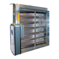
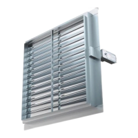
The Actionair PTC Damper is a versatile device designed for both horizontal and vertical airflow applications in various ductwork systems. This range includes Smoke/Shield PTC, Vent/Shield PTC, Hot/Shield PTC, and Hot/Shield Vent PTC models, each tailored for specific safety and operational requirements. These dampers are critical life safety products, engineered to provide fail-safe operation under specific conditions, such as smoke, fire, or loss of electrical power.

Function Description

The primary function of the PTC Damper is to control airflow in ductwork systems, specifically in response to smoke, fire, or thermal events.

  • Smoke/Shield PTC (Modes 1, 5 & 6): These dampers are designed for smoke control, featuring a fail-safe spring close mechanism. In the event of a smoke detection or power loss, the damper blades will automatically close to prevent the spread of smoke. They can be reset manually or electrically, depending on the mode.
  • Vent/Shield PTC (Modes 5 & 6): These models are also designed for smoke control but operate with a fail-safe spring open mechanism. This means that upon activation or power loss, the damper blades will automatically open, typically to facilitate smoke extraction. They also offer manual or electrical reset options.
  • Hot/Shield PTC (Modes 5 & 6): These dampers are specifically designed for fire resistance, capable of operating up to 300 °C for one hour. They feature a fail-safe spring closure, ensuring that in a fire event, the damper blades close to compartmentalize the fire and prevent its spread through the ductwork.
  • Hot/Shield Vent PTC: Similar to Hot/Shield PTC, these dampers are fire-resistant up to 300 °C for one hour but operate with a fail-safe spring opening. This configuration is typically used in fire ventilation systems where opening the damper is necessary to exhaust hot gases and smoke during a fire.

The control modes (Mode 1, Mode 5, and Mode 6) dictate the operational characteristics and reset mechanisms. Mode 1 is a manual system with spring instant closure via a mechanical fusible link. Modes 5 and 6 are electrically operated, with Mode 5 typically for 24V systems and Mode 6 for 230V systems. These modes allow for power-on damper opening and power-off spring closure (or opening for Vent/Shield and Hot/Shield Vent models), or release via an Electrical Thermal Release (ETR). The ETR is a crucial safety feature that triggers the damper's fail-safe action when a specific temperature threshold is reached.

Usage Features

The PTC Dampers are designed for ease of installation and access, with control modes located outside the ductwork.

  • Installation Flexibility: Control Modes 5 and 6 can be fitted in three orientations (vertically down, horizontally, or vertically up) by repositioning the location plate and control mode on the snaplock™ Drive Interface. This flexibility minimizes the room required for the damper and control mode.
  • Mechanical Fusible Link (Mode 1): For Mode 1, a mechanical fusible link is installed in the ductwork. This link melts at a predetermined temperature, triggering the damper to close. The unit cannot be reset if the fusible link is not correctly installed, serving as a safety interlock.
  • Electrical Thermal Release (ETR) (Modes 5 & 6): The ETR is a critical component for electrically operated modes. It should be mounted through the ductwork, ideally in the top half, and both screws must be fully tightened to ensure proper operation. If the ETR is not fitted or is damaged, the unit will not operate, highlighting its importance as a safety feature. A manual test switch on the ETR allows for periodic testing of the damper's fail-safe release.
  • Position Indication: Many models include an external mechanical position indicator with a pointer, providing visual confirmation of the damper blade's status (open or closed).
  • Wiring: All wiring must comply with IEE and BS regulations and be carried out by a competent person. The control modes come with a halogen-free, low smoke and fume electric cable for convenient on-site wiring, ensuring electrical terminations are outside the duct to prevent in-duct fire hazards from wiring faults.
  • Safety Precautions: Users are warned to handle and install dampers with care, as they can close without warning, especially during power loss or fire signals. It is crucial not to introduce any items, fingers, or limbs between the blades. The weight of the unit should be checked, and suitable handling techniques adopted.
  • Ductwork Integration: When fitting ductwork, it must be independently supported and not rely on the damper as a structural anchor. Access doors should be fitted as required by DW144. For Hot/Shield PTC and Hot/Shield Vent PTC dampers fitted to thickened fire-rated ductwork, specific notes on page 7 should be consulted.
  • Multiple Assemblies: Square and rectangular casings are available in multiple module arrangements, supplied with blanking strips for site assembly. Additional support and allowance for thermal expansion (4mm/metre) are necessary for multiple assemblies.

Maintenance Features

Regular maintenance is essential to ensure the continued reliable operation of PTC Dampers, which are life safety products.

  • Planned Inspection Programme: Dampers should be subject to a planned inspection programme, cleaning, and light oil lubrication in accordance with good industry practice.
  • Periodic Testing: For electrically operated units (Modes 5 & 6), it is recommended to periodically test the unit by pushing and holding the test switch on the ETR to confirm that the damper releases. This simulates actual fail-safe release under smoke/fire conditions.
  • Resetting Procedures: After a release event, the damper must be manually reset using a spanner (for Mode 1) or electrically reset (for Modes 5 & 6). It's important to ensure the fusible link or ETR is correctly installed before attempting to reset the unit.
  • Troubleshooting Guide: The manual includes a troubleshooting guide to address common problems such as the interface mode assembly not fitting, the control mode not latching, electrical operation issues, or limited damper movement. This guide provides detailed actions and references to the main document for comprehensive solutions.
  • Environmental Considerations: While designed for normal dry filtered air systems, dampers exposed to fresh air intakes or inclement conditions may require more regular maintenance. Specialist or aggressive environments may be unsuitable for these dampers, and consultation with the Customer Service department is advised if concerns arise.
  • Warranty Information: Modifications made to the units will invalidate warranties, emphasizing the importance of adhering to installation and operating instructions.
  • Customer Service Support: For assistance with applications not described in the manual, or for details on incorporating thickened fire-rated ductwork, the Customer Service Office should be contacted. All installations must comply with the approval of the relevant local authority.

actionair Smoke/Shield PTC Specifications

General IconGeneral
TypeSmoke/Shield PTC
MaterialGalvanized steel
ApplicationHVAC systems
Control24V AC/DC
Temperature Rating250°F (121°C)
StandardsUL 555S

Related product manuals