EasyManua.ls Logo

actionair SmokeShield PTC - User Manual

Default Icon
4 pages
Print Icon
To Next Page IconTo Next Page
Loading...
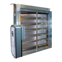
Smoke Shield PTC - 'E S' RATED FIRE DAMPER (Fire & Smoke barrier)
Installation, Operating & Maintenance Instructions
www.actionair.co.uk
For clarity, damper not shown installed in
supporting wall construction, please refer
to the Actionair approved Fire and Smoke
Dampers Installation Manual. The latest
version can be found on our website:
www.actionair.co.uk
Health and Safety
All wiring should be carried out in accordance with the wiring details provided, the IEE and BS regulations, by a competent person.
Care must be taken when installing and inspecting dampers, as they are likely to close without warning due to loss of electrical
power, or a temperature rise in the ductwork. This is their prime function.
Do not introduce any items, fingers or limbs between the blades.
Larger dampers are heavy and must be handled in accordance with current regulations and good practice.
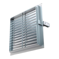
July 2013 SmokeShield PTC Damper Control Modes
Control Mode Installation Procedure
Remove transit plate and recycle.
Slide the interface and mode assembly into the shroud, ensuring that the
slots in the interface casing and the drive coupling, located on the rear of the
interface, are in line.
Push the assembly fully home until the interface sprung retaining pin
engages through the locating hole in the damper shroud (snaplock™).
The control mode can be fitted in any of three orientations i.e. Vertically
down, Horizontally and Vertically up, if you have an space restrictions. This
can easily be carried out by;
Remove and retain the screw (8mm A/F) and washer, through the
position indicator on the control mode.
Remove the control mode and location plate.
Taking care not to disturb the drive hexagon, replace the location
plate, and control mode in the new orientation.
Replace the washer and screw tight (Max 5Nm)
Select a suitable position for the Electrical Thermal Release (ETR)
to be mounted through the ductwork. Ideally this should be in the top half of
the duct and/or above the level of the interface.
Apply the self-adhesive template (located on the rear of the ETR) and drill
the necessary holes (Ø3mm & Ø9.5...Ø11mm).
Push the ETR through the duct and ensure that both screws are used to
hold it in position. Both screws should be tightened fully to ensure that both
sections of the ETR are closed together. This is a safety feature and should
both sections not be closed the unit will not operate.
For ductless installations the ETR should be fitted onto the damper spigot
(not
casing) above the damper interface shroud, and in accordance with the
fitting instructions.
If the ETR is not fitted in the exact manner described above, the unit
will not operate.
The damper should be manually reset and released using the winder
provided, to ensure that correct mechanical operation is achievable.
It is possible to mechanically lock open the SmokeShield PTC damper to
allow air to pass through it by using the winder provided. This may be
necessary if electrical power is not yet available. However, the ETR is not
operable in this instance and the damper will not release automatically
should the temperature rise or a fire occur.
The unit must be wired as detailed.
When power is available, the unit must be checked for correct
electrical operation. Power on to reset, power off to release.
The unit must also be checked by pushing and holding the test switch on the
ETR to confirm that the damper releases. When pressure is removed from
the switch, the damper resets. This may also be done after the initial
installation test, to provide periodic operation of the damper to simulate
actual fail-safe release under smoke/fire conditions.
The ETR cable must not cut to shorten or lengthen, and care must be taken
not to damage it. Either will render the unit inoperable and void any
warranties. This is due to a built in safety feature.
0832-CPR-P0002
Question and Answer IconNeed help?

Do you have a question about the actionair SmokeShield PTC and is the answer not in the manual?

Summary

Health and Safety

Installation, Operating & Maintenance Instructions

General guide for installation, operation, and maintenance of the damper.

Control Mode Installation Procedure

Electrical Thermal Release (ETR) Mounting

Guidance on selecting position and mounting the ETR.

Manual Reset and Release

How to manually reset and release the damper using the provided winder.

Electrical Operation Check

Procedures for checking electrical operation and testing the ETR.

Control Mode Wiring Procedure

Smoke Shield Mode 5 PTC (24 V System)

Wiring details and specifications for the 24V system mode.

Smoke Shield Mode 6 PTC (230 V System)

Wiring details and specifications for the 230V system mode.

Smoke Shield Mode 5-3 P PTC (24 V System)

Wiring for the 24V system with a 0-10V control signal.

LPCB Certification and Product Details

Product Brochure QR Code

QR code to access the smart phone version of the product brochure.

Troubleshooting

Overview

The SmokeShield PTC is an 'E S' rated fire damper designed as a fire and smoke barrier. This device is crucial for health and safety in buildings, as it prevents the spread of fire and smoke through ductwork.

Function Description

The SmokeShield PTC damper's primary function is to automatically close upon loss of electrical power or a rise in ductwork temperature, acting as a fail-safe mechanism. It is designed to be integrated into building management systems for comprehensive fire and smoke control. The device incorporates an Electrical Thermal Release (ETR) which triggers the damper to close when a specified temperature is reached.

Important Technical Specifications

The SmokeShield PTC is available in several control modes, each with specific electrical requirements and operational characteristics:

Smoke Shield Mode 5 PTC (24V System):

  • Supply: AC/DC 24V, 50/60 Hz.
  • Operation: Damper motors open with supply on; damper spring close with supply off.
  • Power Consumption: 12.5 VA, 10/2 W.
  • Max Current (Imax): 8.3A @ 5ms.
  • Spring Close Time: ~22 seconds.
  • Motor Open Time: ~60 seconds.
  • Temperature Range: -30°C to +50°C (continuous).
  • IP Rating: IP54.
  • ETR: Must be fitted to ducting for damper operation.
  • Volt Free Contacts:
    • Made between 1 & 2 when damper fully released.
    • Made between 4 & 6 when damper fully reset.
  • Supply: Typically 10W (motoring), 2W (reset).

Smoke Shield Mode 6 PTC (230V System):

  • Supply: AC/DC 230V, 50/60 Hz.
  • Operation: Damper motors open with supply on; damper spring close with supply off.
  • Power Consumption: 14 VA, 12/4 W.
  • Max Current (Imax): 8.3A @ 5ms (not explicitly stated for Mode 6 but common for similar devices).
  • Spring Close Time: ~22 seconds.
  • Motor Open Time: ~60 seconds.
  • Temperature Range: -30°C to +50°C (continuous).
  • IP Rating: IP54.
  • ETR: Must be fitted to ducting for damper operation.
  • Volt Free Contacts:
    • Made between 1 & 2 when damper fully released.
    • Made between 4 & 6 when damper fully reset.
  • Supply: Typically 12W (motoring), 4W (reset).
  • Isolation: System must incorporate a device to disconnect phase conductors with at least 3mm contact gap for main power supply isolation.
  • 120V A.C. version available.

Smoke Shield Mode 5-3P PTC (24V System):

  • Supply: AC/DC 24V, 50/60 Hz.
  • Operation: Damper motors open with supply on; damper spring close with supply off.
  • Control Signal: Controlled by a standard 0...10V control signal. The actuator motors to the position specified by the control signal.
  • Fail-Safe: If the ETR is activated, power supply lost or removed, the device springs the damper to the fail-safe position.
  • Power Consumption: 9.5 VA, 7/2.5 W.
  • Max Current (Imax): 8.3A @ 5ms.
  • Spring Close Time: ~16 seconds.
  • Motor Open Time: ~120 seconds.
  • Temperature Range: -30°C to +50°C (continuous).
  • IP Rating: IP54.
  • ETR: Must be fitted to ducting for damper operation.
  • Volt Free Contacts:
    • Made between 1 & 2 when damper fully released.
    • Made between 4 & 6 when damper fully reset.
  • Supply: Typically 6W (motoring), 2W (holding).
  • Control Signal (Y): DC 0...10V.
  • Control Signal (U): DC 2...10V.
  • Note: For intermediate positions, neither of the contact conditions (closed/open) will be true.

General Specifications:

  • Cable: One metre of halogen-free low smoke and fume electric cable is fitted to each control mode.
  • ETR Cabling: Prewired with 0.5m halogen-free low smoke and fume cabling to Control Modes 5 and 6.
  • Sensing Element: Response temperature: 72°C.
  • Closure Times: M5 & 6: ~22s (@tamb = 20°C); M5-3P: ~16s (@tamb = 20°C).
  • Corrosion Tested: To En 60068-2-52: Pass.
  • Operational Reliability: 20,000 cycles: Pass.
  • Ambient Leakage Test: Pass.
  • Certifications: LPCB LPS 1162: Issue 4, Cert No: 017a/04; CE 0832-CPR-P0002; Assessed to ISO 9001:2008 (LPCB Cert No. 17).

Usage Features

Installation:

  • Safety First: All wiring must be carried out by a competent person according to wiring details, IEE, and BS regulations. Dampers are heavy and require proper handling.
  • Transit Plate Removal: Remove and recycle the transit plate.
  • Interface and Mode Assembly: Slide the interface and mode assembly into the shroud, aligning slots and the drive coupling. Push until the sprung retaining pin engages (snaplock™).
  • Orientation: The control mode can be fitted in three orientations (vertically down, horizontally, vertically up) to accommodate space restrictions. This involves removing and retaining a screw and washer, removing the control mode and location plate, replacing the location plate, and then the control mode in the new orientation, finally replacing the washer and screw (Max 5Nm).
  • ETR Mounting: Select a suitable position for the ETR through the ductwork, ideally in the top half of the duct and/or above the interface level. Use the self-adhesive template to drill the necessary holes (Ø3mm & Ø9.5...Ø11mm). Push the ETR through the duct and secure it with both screws, ensuring both sections are closed together for the unit to operate.
  • Ductless Installations: For ductless installations, the ETR should be fitted onto the damper spigot (not casing) above the damper interface shroud, following fitting instructions.
  • Critical Note: If the ETR is not fitted exactly as described, the unit will not operate.
  • Manual Reset: The damper should be manually reset and released using the provided winder to ensure correct mechanical operation.
  • Mechanical Lock Open: The SmokeShield PTC damper can be mechanically locked open with the winder if electrical power is unavailable. However, in this state, the ETR is inoperable, and the damper will not automatically release if temperature rises or a fire occurs.
  • Wiring: The unit must be wired as detailed in the provided diagrams.

Operation:

  • Electrical Operation Check: Once power is available, check for correct electrical operation: power on to reset, power off to release.
  • Test Switch: The unit must also be checked by pushing and holding the test switch on the ETR to confirm damper release. Releasing pressure from the switch resets the damper. This test can be performed after initial installation and periodically to simulate fail-safe release.
  • Integration: For integration with Actionpac damper control systems (LNS, EMS, or EMB), refer to relevant catalogues and project details.

Maintenance Features

Troubleshooting:

  • Damper drive shaft not in line with shroud: Gently adjust blades to fully closed.
  • Mode not in released position: Release clutch on motor using manual key. Check the slot on the rear of the interface.
  • Slots on non-access side of shroud blocked: Ensure adequate clearance.
  • ETR not correctly fitted to duct: Screw fix to duct, ensuring both parts of ETR are fully together (do not overtighten).
  • Mode incorrectly wired: Check wiring according to procedures.
  • ETR cables damaged/tampered with: Replace with new mode.
  • Mode not correctly synchronised with interface: Remove motor from interface. Check motor in fully released state. Set position of interface, and refit motor with label upmost, including motor location pointer and washer.
  • Damper damaged or poorly installed: New damper or re-install.
  • Interface not fitted correctly to damper: Fit interface correctly, ensure retaining pin protrudes through location hole in the shroud.
  • Foreign matter impeding blade movement: Check and remove.
  • Motor location pointer omitted: Fit new pointer.
  • Mode not screwed down correctly: Check and tighten.

General Maintenance:

  • ETR Cable Integrity: The ETR cable must not be cut, shortened, or lengthened, and care must be taken not to damage it. Any alteration will render the unit inoperable and void warranties due to a built-in safety feature.
  • Periodic Operation: The manual test switch on the ETR allows for periodic operation of the damper, simulating actual fail-safe release under smoke/fire conditions, which is a key maintenance check.
  • Documentation: Refer to the Actionair approved Fire and Smoke Dampers Installation Manual for detailed installation and maintenance procedures. The latest version is available on the Actionair website.

actionair SmokeShield PTC Specifications

General IconGeneral
Brandactionair
ModelSmokeShield PTC
CategoryFire and Smoke Dampers
LanguageEnglish

Related product manuals