MV-5502-5503-1-2018 . ACTIV POOL ApS . Ledreborg Allé 128K . DK-4000 Roskilde . Tel.: +45 7022 6856 . web: www.activpool.com
52
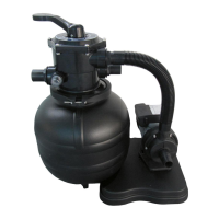
4. FILTER/PUMP INSTALLATION
The lter with pump (Fig.1 ) are employed in ltering above ground and in-ground pools, where
careful and expert water cleaning is required. The lter/pump is positioned at least 3.5 m from the
edge of the pool. The water tem-perature must not exceed 35°.
Disconnect the plug before starting to do any work.
Before installing the lter pump unit, identify the position in which it is to be installed, as once it
has been lled up with sand, the lter is hard to move due to its weight.
Priming
The hoses should be primed so that the sand lter plus the hoses are totally lled with water. Lift
hoses up over sand lter system to help water to run to the pump then lower the hoses again. This
procedure must be done until the sand lter pump and the hoses are lled with water and the
pump itself begins to suck water through. By doing this, the pump creates a vacuum so it is only
needed to be done one time, (if the hoses are not removed in the meantime).
Always place the sand lter system under the water surface in the pool, so that
the water can ow naturally towards the pump. Is it used with an in-ground pool,
you have to place the sand lter system correspondingly lower into a shaft/pit in
the ground, so the water can ow by itself into the pump. Be sure that the shaft/pit
stays dry. There should be an outlet/drain to lead the water out of the shaft/pit.
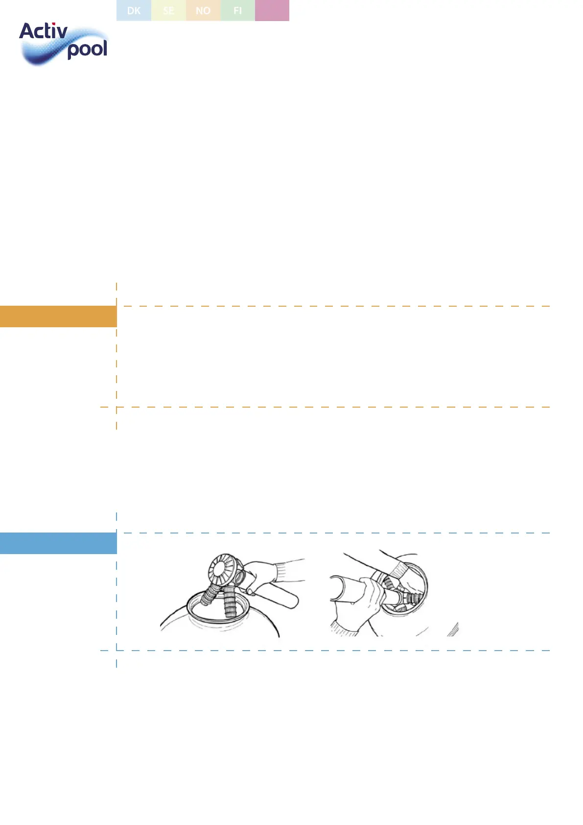
4.1 FILTER INSTALLATION
Insert the tube with the manifold (6) in the tank (Fig. 3) and screw the small sand guard lters (7)
to the manifold (Fig. 4). Place the completed manifold in the middle of the tank and ll ¼ with
water to stabi¬lize the tank and make sure that sand grains sets in the lters during lling.
3 4
Place the spigot (9) on the mouth of the container, to provide sand getting into the manifold
during lling, and make sure that tube is centered on the manifold. Fill ¾ with sand (Fig. 5).
Remove the spigot, clean the lter mouth carefully and insert the 7-way valve (2) making sure
there is no sand in the tank. (Fig. 6) Insert the gasket (3) and tighten the fastening screws (Fig. 7).
The lter is now ready.
BEWARE
FIGURE
UK
 Loading...