Do you have a question about the ActronAir EVA290T and is the answer not in the manual?
This document is an Installation and Commissioning Guide for ActronAir Variable Capacity Commercial Split Ducted Indoor Units, specifically models EVA290T and EVA330T. It provides comprehensive instructions for the safe and correct installation, operation, and maintenance of these air conditioning systems.
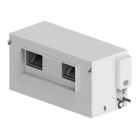
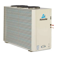
The ActronAir Variable Capacity Commercial Series air conditioning units are designed to provide optimal air conditioning with maximum energy efficiency for commercial applications. These are split ducted indoor units, meaning they are intended for indoor installation, typically within a roof cavity, and connect to an outdoor unit to form a complete air conditioning system. The variable capacity feature allows the system to adjust its output to match the specific cooling or heating demands, leading to improved comfort and energy savings.
Model Numbers:
Overall Nominal Dimensions (H x W x D):
Supply Duct (H x W):
Return Duct:
Drain Connection:
Gas Pipes:
Liquid Pipe:
Unit Weight:
Refrigerant:
Electrical Supply:
Maximum Cable Lengths:
Circuit Breaker Size and Cable Size (EVA290T/EVA330T):
Default Fan Speed Settings (@100Pa):
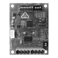
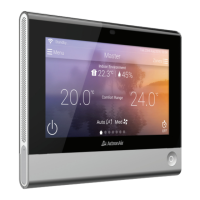
Indoor Installation: The unit is designed for indoor installation, preferably in a roof cavity, requiring a stable and rigid support structure (e.g., roof joists and rafters) for proper weight distribution. Noise and Vibration Minimization: It is recommended to locate the indoor unit away from areas where noise is a critical factor. The use of rubber mounting pads (not supplied) is suggested to minimize noise and vibration transfer to building structures. Duct Connection: The unit comes with a duct flange for easy connection to supply and return air ductwork. Proper sizing of ductwork is crucial to meet airflow and static pressure requirements. Flexible duct connections are recommended between the unit and the duct system to further reduce noise and vibration. Wall Controller Options: The system supports various wall controllers, including NEO and LC7-2 models, with combinations allowing up to three wall controllers. Specific wiring configurations are provided for recommended and alternate setups. Optional Sensors: The unit can integrate with optional sensors such as the LM-RS-2 (remote sensor) and AERSS (duct sensor) for enhanced control and monitoring. EC Indoor Fan Commissioning: The guide details procedures for commissioning the EC indoor fan airflow, which can be done via the Outdoor Unit CPU, NEO/LC7-2 Wall Control, or a 3rd Party Controller. A specific method is provided for manually adjusting fan PWM speed using an on-board potentiometer on the CMI board, allowing for air balancing without an outdoor unit or wall controller connected.
Product Inspections: Upon receiving the shipment, users are instructed to inspect the unit, components, and accessories for any damage and verify model, serial number, and electrical specifications against the nameplate. Condensate Drain: A drain kit (not supplied) is required for external trapping of condensate. The guide provides suggested drainage instructions, including the installation of a condensate safety tray and drain (not supplied) as a recommendation. Return Air Filter: Return air filters (not supplied) are essential for maintaining efficiency and prolonging unit operation, as well as ensuring clean room conditions. They must be placed in an easily accessible location for service and regular cleaning/replacement. Maintenance Frequency Checklist: A detailed checklist is provided for both electrical and indoor section maintenance.
The guide emphasizes that all installation and service work must be performed by licensed HVAC technicians in accordance with prevailing WH&S regulations, local codes, regulations, and building code standards to ensure safety and maintain warranty validity.
| Brand | ActronAir |
|---|---|
| Model | EVA290T |
| Category | Air Conditioner Accessories |
| Language | English |