16
Installation and Commissioning Guide - Split Ducted Variable Capacity Commercial Indoor Unit
Doc. No. 0525 - 068 Ver. 3 201104
Installation and Commissioning Guide
Variable Capacity Commercial
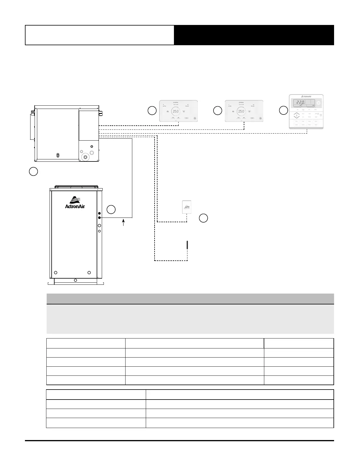
. Wiring Configuration : Recommended
4
INDOOR UNIT
DATA CONTROL
CABLE
3
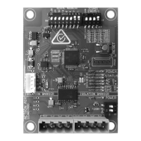
LMRS2
OPTIONAL
AERSS
OPTIONAL
2a
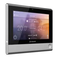
NEO
WALL CONTROLLER
1
OPTIONAL
2b
NEO
WALL CONTROLLER
2
OPTIONAL
LC72
WALL CONTROLLER
3
OPTIONAL
2c
1
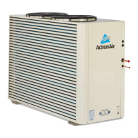
OUTDOOR UNIT
NOTES
• Diagram shown above is a general representation only. Refer to individual unit wiring diagram for complete wiring
connection details.
• Long runs beside Mains cables or TV antenna cables should be avoided where possible.
• Daisy connection is not allowed for NEO wall controller.
Item Description Maximum Cable Length
1 to 4 Outdoor PCB to Indoor PCB 100 m
4 to 2a, 4 to 2b Indoor PCB to Wall Controller 90 m
4 to 2C Indoor PCB to Wall Controller 3 100 m
4 to 3 Indoor PCB to Remote Sensor 100 m
Description Cable Type
LC7-2 and NEO Field Control Wiring Cat5E UTP (AWG 24) Data Cable
Indoor to Remote Sensor Cat5E UTP (AWG 24) Data Cable
Indoor to Outdoor Data Cable 2 Core Shielded Twisted Pair 7/0.30 (0.5mm
2
) Shielded Data Cable


 To Next Page