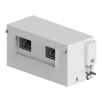
The ActronAir BMS MODBUS 485 is an interface board designed to integrate ActronAir ducted air conditioners with a central or remote Building Management System (BMS) using the Modbus RTU protocol over RS-485. This kit provides enhanced control and monitoring capabilities for the air conditioning system, aiming for optimal comfort, efficient operation, and energy savings.
Function Description:
The ICUNO-MOD Modbus RS-485 BMS Card enables communication between the UNO Outdoor Board of ActronAir air conditioners and a customer's BMS system. Each unit on the Modbus RS-485 network requires a unique address for proper identification and communication. The device supports both Basic BMS Control and Advanced BMS Control modes, offering varying levels of system interaction.
In Basic BMS Control, the system operating logic is managed by the ActronAir on-board controls, providing a straightforward BMS solution. This mode allows the BMS to:
- Turn the system on/off.
- Adjust room setpoint temperature.
- Change the mode of operation (Auto/Cool/Heat/Fan Only).
- Change the supply fan settings (Low/Medium/High/Auto).
- Set the supply air filter notification timer.
- Open and Close zones.
When operating in Basic BMS Control with a Wall Control, all settings changes from both the BMS and Wall Control are synchronized across the entire system.
In Advanced BMS Control, the system offers more complex and bespoke scenarios, suitable for applications where the air conditioning needs to link with other products or requires customized functions not included in the existing on-board controls. Even with highly customizable control, ActronAir software maintains safety logics to prevent operational problems. In this mode, the BMS can:
- Turn the system on/off.
- Control compressor capacity.
- Set supply fan speed.
- Control Heat/Cool (reversing valve – on/off).
- Set the supply air filter notification timer.
- Open and Close zones.
A Wall Control cannot be used if the ActronAir AC system is configured for Advanced BMS Control.
Important Technical Specifications:
- Device Type: Slave
- Baud Rates: 9600 (Default), 19200, 38400, 76800, 115200. The Baud Rate and Data Parity must be consistent across all devices on the RS-485 network to avoid communication errors.
- Data Parity: Even (Default), None.
- Unit Load: 1/32
- Device Address Range: 1 – 247. Each device must have a unique serial address.
- Protocol: Modbus RTU
- Electrical Interface: RS-485, 4 Wire (2 pair)
- Cable Type: Twisted Pair Shielded Cable.
- Recommended Wire Size: 0.5mm² (7/0.30).
- Connector Type: Screw terminals.
- Supported Function Codes:
- 03 – Read Holding Registers
- 06 – Write Single Register
- 16 – Write Multiple Registers
- Broadcast: Yes
- Maximum Network Cable Length: 1000 meters (@9600 baud rate).
- Standard: Modbus over serial line v1.0.
- Power Supply: The board receives power from the UNO Outdoor Board.
- Isolation Barrier: The ICUNO-MOD features isolation barriers for both power and communication lines (BMS IN/OUT) to prevent ground loops and ensure robust operation.
Usage Features:
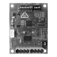
- DIP Switches: The board features SW1 (SERIAL ADDRESS DIP SWITCH) for configuring the Modbus serial address and SW2 (BMS SETTINGS DIP SWITCH) for configuring Baud Rate and Data Parity. SW3 (TERMINATION DIP SWITCH) is used to enable 120Ω termination at the start or end of the Modbus RS-485 network.
- RESET Button: A PROG RESET push button is available on the board to re-initialize the BMS card and apply new configurations after DIP switch changes or power cycles.
- LED Indicators:
- Red Power LED: Indicates power to the BMS Card (ON when powered).
- Amber Status LED: Indicates successful communication with the A/C unit (ON when stable connection).
- White Status LED: Indicates successful communication with the BMS controller (ON when active and sending commands).
- Blue AC Tx/Rx LEDs: Indicate data transmission (Tx) and reception (Rx) with the A/C unit.
- Amber BMS Tx/Rx LEDs: Indicate data transmission (Tx) and reception (Rx) with the BMS master.
- Modbus Registers: A comprehensive set of Modbus registers are available for monitoring and control, including:
- Basic Unit Control: AC On/OFF, Supply Fan Mode, Air Filter Notification/Timer, Mode of Operation, Master Setpoint Temperature, Supply Fan Controls.
- Unit Status: Alarm Output, BMS Demand Mode, Air Filter Notification/Run Timer, Actual System Running Capacity, Room Temperature, Outside Air Temperature.
- Zone Control: Individual zone On/Off control for up to 8 zones.
- Unit Faults: Current Error Code, Error History Log (up to 5 errors), No Communications with Indoor/Outdoor Unit, Room/Outside Air Temperature Sensor Status.
- Model Information: Outdoor Unit Model, Software Version, Compressor Type.
- Compressor Status: Running status, Heating status, Demand, Speed, Unit Defrosting, Suction/Discharge Pressure/Temperature, Suction Superheat/Target, LP/HP Switch Trip/Lockout.
- Coil Temperatures: Outdoor Coil 1 Temperature, Indoor Coil Temperature.
- Fan Speeds: Outdoor Coil 1 Fan Speed Setting, Indoor Coil 1 Fan 1 Speed (0.1% and RPM).
- EEV Position: Compressor 1 EEV position.
- Temperature Status: Compressor 1 Discharge Temp High, LP/HP Status, Suction/Discharge Temperature Status, Outdoor/Indoor Coil Temperature Status.
- Room Temperature Sensors: Wall Control 1, 2, 3 Temperature, Auxiliary Sensor 1, 2, 3 Temperature (for residential systems only).
Maintenance Features:
- Troubleshooting Table: The manual provides a detailed troubleshooting table linking LED indications and symptoms to probable causes and suggested resolutions, such as checking cable connections, replacing the BMS card, confirming serial address/baud rate settings, and checking for network noise.
- Filter Notification: The system includes a return air filter notification feature, allowing users to set a timer for filter cleaning. The Air Filter Alarm (Modbus Analog 506) is triggered when run hours equal the timer, and can be reset via Modbus (Modbus Analog 6) after cleaning.
- Error Logging: The unit logs up to 5 error codes in its history (Modbus Analog 901-905), aiding in diagnostics.
- Isolation: The RS485 on the ICUNO-MOD is isolated to prevent ground loops, enhancing system reliability and reducing maintenance issues related to electrical interference.
- Software Updates: The BMS Card Software Version (Modbus Analog 405) can be read, which is useful for support and potential future updates.
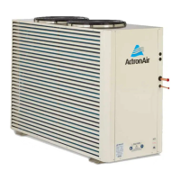
The installation process emphasizes safety, requiring power isolation, lockout/tagout procedures, and anti-static precautions due to the sensitive electronic components. The module is designed for OUTDOOR and Packaged unit use, requiring installation away from excessive dust, heat, and moisture.