Installation and Commissioning Guide
ICUNO-MOD
9
8
Installation and Commissioning Guide ICUNO-MOD
Doc. No. 9590-3013 Ver. 5 200722
ActronAir is constantly seeking ways to improve the design of its products, therefore specifications are subject to change without notice.
Copyright © 2019 Actron Engineering Pty. Ltd.
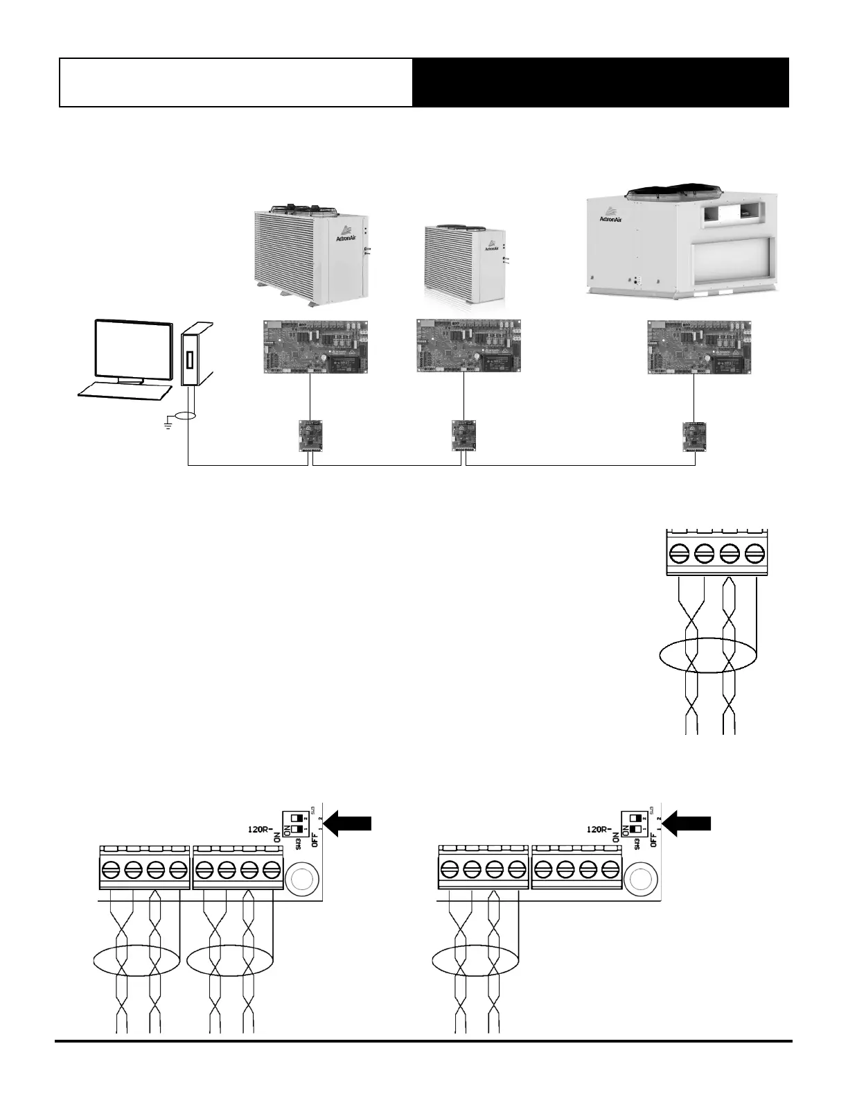
04.04. BMS Installation Procedure
INTERMEDIATE
BMS DEVICE
LAST BMS DEVICE
CUSTOMER BMS MASTER
INTERMEDIATE
BMS DEVICE
ICUNOMOD
ICUNOMOD
ICUNOMOD
SHIELDDRAIN
WIRE
Step 1. Recommended Cable Size: 0.5mm² (7/0.30)
• Use 0.5mm² (7/0.30) two twisted pair shielded data cable to connect to the A,B,COM and
SCRN terminals of either of the two BMS connectors.
• One of the twisted pair cables must be used to connect the A terminals of each of the
Modbus RS-485 devices on the network. The other cable, from the same twisted pair,
must be used to connect all the B terminals.
• The other twisted pair should be joined together and connected to the COM terminal.
• Connect the Screen wires to the SCRN terminal of the connector.
Note: COM and SCRN must be connected to ICUNO-MOD. On the BMS control end, ensure COM and
SCRN are connected to the same earth as the BMS controller. The RS485 on the ICUNO-MOD is
isolated to prevent ground loops.
Step 2. If another Modbus RS-485 device is to be connected on the same network, then use the
other BMS Connector to daisy chain additional devices.
Step 3. If the BMS device is connected at the start or the end of the Modbus RS-485 network, the
120 termination SW3 DIP switch must be turned on.
Note: It is required to earth the shield wire of the data cable at the BMS Master end.
SW3
TERMINATION
DIP SWITCH
INTERMEDIATE BMS
DEVICE
SW3
TERMINATION
DIP SWITCH
LAST BMS
DEVICE