Installation and Commissioning Guide
ICUNO-MOD
7
6
Installation and Commissioning Guide ICUNO-MOD
Doc. No. 9590-3013 Ver. 5 200722
ActronAir is constantly seeking ways to improve the design of its products, therefore specifications are subject to change without notice.
Copyright © 2019 Actron Engineering Pty. Ltd.
04. ICUNO-MOD Installation Procedure
04.01. Installation for Variable Capacity Commercial
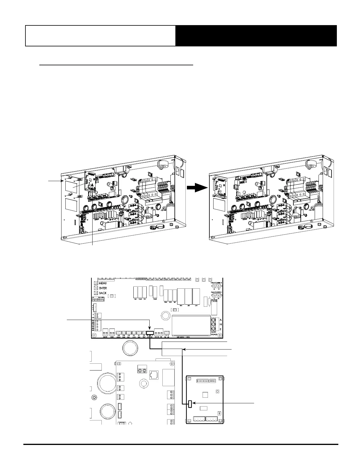
To install ICUNO-MOD Interface Board into the Outdoor Electrical Panel and to UNO Outdoor Board
Step 1. Isolate and fit electrical lockout device and TAG to the main circuit breaker for the system you are working on,
before removing the Electrical Panel Cover.
Step 2. Open Electrical Panel Cover.
Step 3. Test unit with multimeter to ensure there is no power, before starting installation of the BMS card.
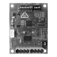
Step 4: Use supplied PCB Mounts to mount ICUNO-MOD into correct location.
NOTE: Location will differ between ActronAir systems.
PCB
MOUNTS
ICUNOMOD
Step 5. Use the Data Cable provided to connect the BMS card (marked OUTDOOR AUX) 4 Pin socket port to the OUTDOOR
BOARD (marked AUX 485) 4 Pin socket port.
DUCT RAIL
UNO OUTDOOR BOARD
ICUNOMOD
INTERCONNECTION CABLE: ENSURE
TO ROUTE THIS CABLE THROUGH
THE DUCT RAIL.
AUX 485
OUTDOOR AUX
NOTE: The layout will differ between ActronAir systems.