10
11
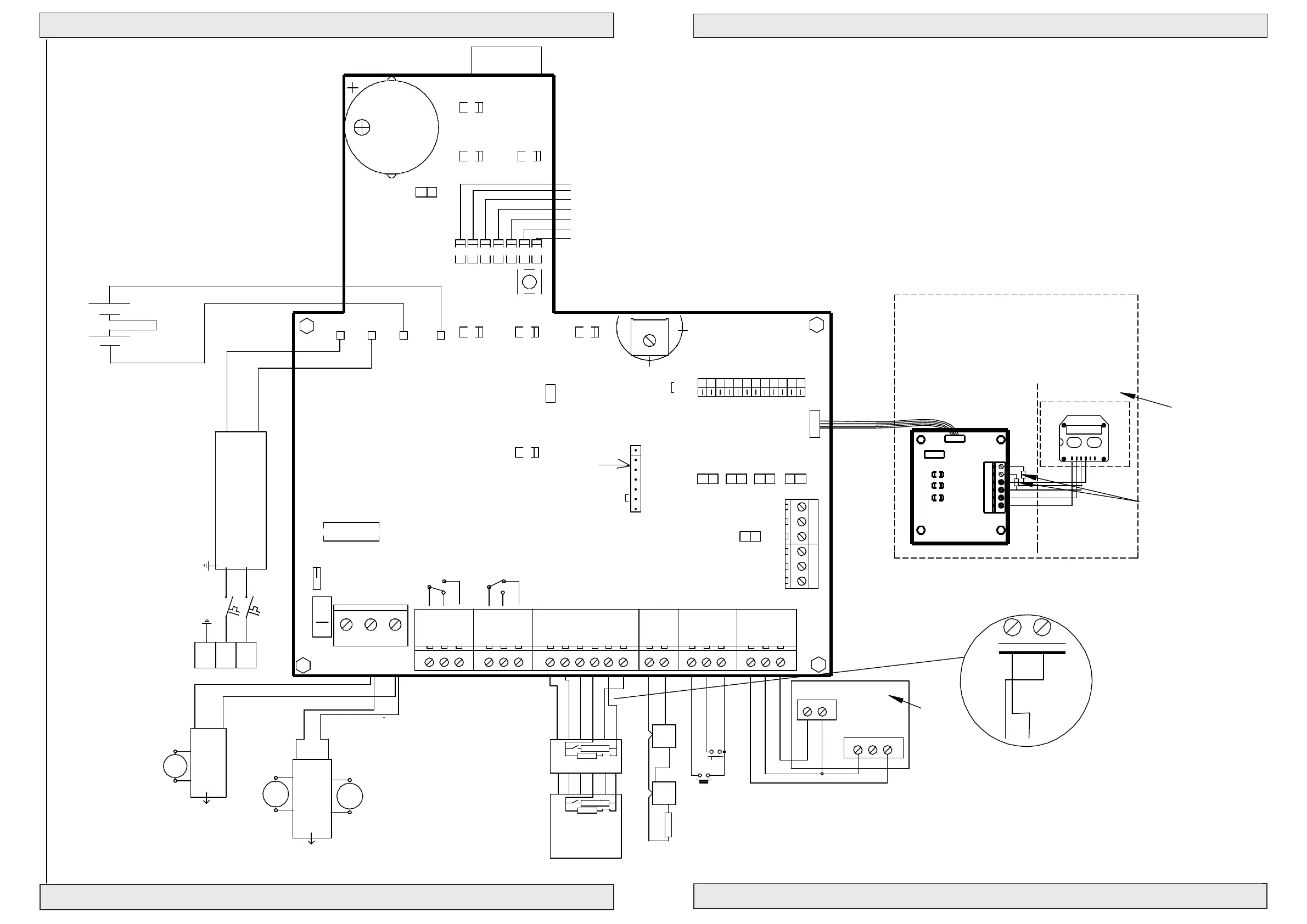
Control for Fire and Comfort Ventilation Type SVM 24V-5A / SVM 24V-8A
Control for Fire and Comfort Ventilation Type SVM 24V-5A / SVM 24V-8A
#111960
#111961
AW R-24
NC
24V
NO
COM
AC/DC
Next LIP
Next LIP
Blue
Brown
2 channel LIP 6
Max. Torque 0.5 Nm
2,2KΩ
Blue
1 Cannel LIP 7
M2
21
5
6
LIP #2
M1
8
7
34
Brown
Keyboard
#121615
Max. Torque 0.5 Nm
See page 12
}
61
Fit J1 in last BVT for
OPENCL OS E
RED
ALARM
GRE
OK
YEL
FAILURE
J1
BUZZER ON/OFF
RED
RED
RED
BL
Yellow LED
RED
RED
J15
Fire switch type BVT.
DIP settings see page 13
24V Out
PS1
Remove resistors when
LD7 BUS failure (red). Lit when local unit is not recieving signal.
BRA
TEMP DETECT
SERVICE TIMER
SNITCH
FAIL RELAY M.
WEEK OPEN
AG MODE
SPRINKLER
BUS COMFORT
BU S FIR E
123 4 6 75 8 119 10
Exte rn a l fire swi tch
Green LED
mounting priorityswitch
LD3 Weather sensor active (red). Lit when weather sensor is active.
LD6 Line failure smokesensor (red). Lit for line fail. on smokes.
comfort features
Con. Fire . Sw
FAIL SAFE
Min
C
o
n
s
t
.
BATT LOW
P
u
l
s
v
a
r
i
a
b
l
e
YEL
RESET
LINE FAILAC FAIL
BUS Slave
Ext 3 wire monitor (line 1)
LD2 Actuator closing (green). Lit when actuator is closing.
LD5 Line failure fire switch (red). Lit for line failure on fire switch.
END termination
YEL YEL
BAT +
BAT -
ON
→
START termination
DOME OPEN
BLUE
PS +
PS -
-
+
+
Black 2,5mm2
-
Puls
Max.
Potmeter for
- 24VDC +
Batteries 2x 12V - 7,2 Ah
24V Red 2,5mm2
Connection
→
J5 J6 J7
SLAVEMASTER
SVM 24V - 5A/8A
END TERM.
A3 B1 B2
BUZZER
B3
→
→
Serial Out
next unit.
Connection to
→
2120
Gnd
2322
Weather
Gnd
24V
A2
→
A1
Serial In
Connection from
Bus connection for serial connection
up to 35 pcs. control units.
of terminal 23
18
Up
17
Smoke
16
Gnd
19
Down
13
24V
ALARM
Fail. 24V
1211
FIRE
Gnd
15
Reset
14
COM
7
NO
NC
98
Failure OutAlarm Out
NC
5
COM
4
NO
6
3
OK 24V
10
START TERM.
L1 Out
L1 In
No.1
L2
L1 In
L2
Up
2,2KΩ
Fire switch BVT No. 1
10 KΩ
1 32 6 74
prev. unit.
→
Extra relay print #111655
GRE
DIP NO
→
1
RED
LD1 Actuator open (red). Lit when actuator is opening.
LD4 Line failure actuator (red). Lit for line failure on actuator.
each 30V 0,5A
Potential free ALARM switch.
Max 48V 0,5A
heat sensors
Smoke or
Down
(Close all)
10 KΩ
L1 Out
Comfort
1
2
34
2
J4
Set J11 for batteri backup
provides 4 additional
OFF
Firemands Priority Switch
Max 48V 0,5A
Potential free Failure switch.
line monitoring
(only last sensor)
1 23 4
7
6
Nr.2-20
Switch
Max. 8A
FUSE F1 - fast
J 34
J2
12
Line 1
1
2
N1
3
13 A Autofuse
PE L1
1
Blue
2
M1
Brown
1
2
7
6
10 KΩ
potential free switches
6
LIP #1
5
Actuator
Actuator
24VDC 150W/200W
NTC
J9
Without keyboard jumper mounted
Com + NO connected on alarm.
Com + NC connected on failure.
REMOTE
Motor line monitor
Power Supply 180-250 VAC
no: 111894
SWM Add-on
Power
Open
Close
LED 1 Green
LED 3 Red
LED 2 Red
GND
LED
OPEN
CLOSE
1
J1
J1
2
J11
Red LED
BUS Master
3
4
5
6
To start communication
LD3 + LD2 flashes for
5 sec. when flatcable
is connected.
LD1 (power) will
illuminate when power is on.
If LD2 (fireswitch) illuminates
linefault on fireswitch.
If LD3 (fireclose) illuminates
linefault on fireclose.
Connection diagram SVM24
Drawing: 211704 N