14
15
Control for Fire and Comfort Ventilation Type SVM 24V-5A / SVM 24V-8A
Control for Fire and Comfort Ventilation Type SVM 24V-5A / SVM 24V-8A
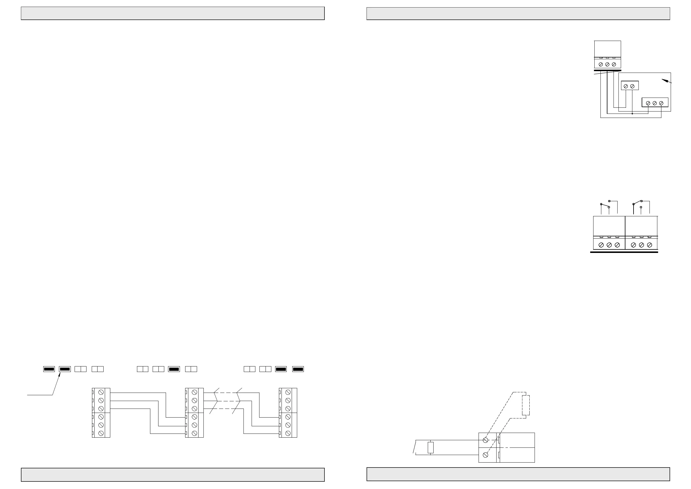
Connection of more controls to one re group (bus connection)
By means of a bus communication it is possible to make 2 – 35 control panels to work as a complete
system. The control panels communicate with each other via a 3 wire bus connection. This could e.g. be a
3x0.5 mm² reproof cable.
Terminal no. A1, A2, A3 are for the incoming connection and B1, B2, B3 for the outgoing connection.
In the rst control panel start Bus J4 has to be on. This control is Master and J5 must therefore also be on.
The bus cable is connected on the output terminals B1, B2, B3 and lead to the next control panel which
is a slave, J6 must therefore be on. The cable is connected to the input terminals A1, A2, A3 of the next
control panel and further to the next slave control panel from terminal B1, B2, B3. In the last slave control
panel J7 and J6 must be on in order to terminate the bus connection.
ALARM: Alarms from Manuel Control Point smoke-/heat detectors are controlled locally. When DIP11 is
set the panel will go into alarm state if another control panel connected on the BUS enters alarm state
RESET: If the reset button on one control or in one re switch is activated, the reset function on all
connected controls is activated and starts the closing function on all motor output in approx. 180 sec.
COMFORT: The comfort control can work locally on each control panel. When DIP 10 is set the control
panel will react on any comfort signal send on the bus from another control panel.
If a wind- and rain sensor is connected, it will work on all control panels on the bus no matter dip settings.
Function description for control panels connected with bus connection
If more control panels are connected by means of a bus connection, the following are monitored/
communicated between the control panels:
- A detected bus error makes the LED LD7 on the main board light/ash.
- A detected bus error brings all controls on the bus connection in error condition (line error).
- If one of the control panels in the network goes into alarm condition, all go into alarm condition.
- If one of the control panels goes into a certain error condition (line error, AC error, battery error or
bus error), the other control panels also go into error condition – the type of the error is indicated
on the board of the front plate of all control panels – on the control panel(s) which have not caused
the error, the ok LED on the board of the front plate ashes at the same time as the error. On the
control panel(s) which have caused the error, the OK LED is switched off.
A4
REV:
SIZE:
www.actulux.com
DATE: 26-09-17
TITLE:
SCALE:
Denmark
1:1
DRAWN BY: PSP
DK 9560 Hadsund
Haandvaerkervej 2
2 OF 3
SHEET:
DWG NO.:
211704_06
Actulux A/S Phone int.: +45 98 57 40 90
Fax int.: +45 96 15 28 00
e-mail: info@actulux.com
ENGELSK/TYSK
BUS Master
MASTER
J6
Fireproof
J4
START termination
Slave
BUS connection
Fireproof
Serial InSerial In
Serial Out
Serial Out
B1A3
B2
A1
A3A2
B2B1
A3A2
B2
B1
B3B2B1A3A2
BUS connection
BUS Slave
A1
Last Control Panel on BUS
3x0,5mm²
Serial Out
Serial In
3x0,5mm²
First Control Panel on BUS
Master
START TERM.
J4
MASTER
J5
SLAVE
J6
END TERM.
J7
START TERM.
J4
MASTER
J5
SLAVE
J6
END TERM.
J7
END TERM.
J7
SLAVE
J5
START TERM.
START termination
BUS Master
BUS Slave
END termination
START termination
BUS Master
BUS Slave
END termination
END termination
Please notice
mounted jumpers
Slaver
0-33 Control Panels on BUS
Connection of weather sensor / Close all function
A weather sensor can be connected to the control panel.
The weather sensor is adjusted according to the instructions.
Actuators should be closed when the wind is above 6 m/s.
LED LD3 on the main board indicates active weather sensor - lights
as long as input is active.
As long as the weather sensor is active, motor inputs cannot be opened with
comfort switches.
The weather sensor closes on all controls which are connected through bus
connection.
On the input to weather station a weekly timer can be connected which makes
sure that everything is closed, e.g. by end of a working day.
Power Supply to terminal 22 and 23 is only AC supplied as standard.
If battery backup is needed, then mount J11 .
This is only possible at PCB V5 and following versions.
NOTE: Be aware of standby time due to current consumption.
External signal output, connection to Fire Alarm
Panel and other control systems
The control panel can forward alarm condition to external connected
systems by means of potential free contacts on the terminals 4 (com),
5(NC) and 6(NO).
The control panel can forward failure condition to external connected
systems by means of potential free contacts on the terminals 7 (com),
8(NO) and 9(NC).
Alarm and error contacts work parallel on all controls connected with
bus connection.
DIP6 (fail relay):
On = Fail relay changes function to indicate open/closed window.
How to make a connection from a Fire Alarm Panel
The control panel can receive potential free zero volt alarm signals from e.g.
AFA systems on the input to re switch or smoke-/heat detector
Terminal 16 and 17.
– Line monitoring resistor must be tted on the contact in the AFA system
Normally open
Supplied with Panel
#111960
#111961
AWR-24
NC
24V
NO
COM
AC/DC
Next LIP
Next LIP
Blue
Brown
2 channel LIP 6
Max. Torque 0.5 Nm
2,2KΩ
Blue
1 Cannel LIP 7
M2
21
5
6
LIP #2
M1
8
7
34
Brown
Keyboard
#121615
Max. Torque 0.5 Nm
See page 12
}
61
Fit J1 in last BVT for
OPENCL OS E
RED
ALARM
GRE
OK
YEL
FAILURE
J1
BUZZER ON/OFF
RED
RED
RED
BL
Yellow LED
RED
RED
J15
Fire switch type BVT.
DIP settings see page 13
24V Out
PS1
Remove resistors when
LD7 BUS failure (red). Lit when local unit is not recieving signal.
BRA
TEMP DETECT
SERVICE TIMER
SNITCH
FAIL RELAY M.
WEEK OPEN
AG MODE
SPRINKLER
BUS COMFORT
BU S FIR E
123 4 6 75 8 119 10
Exte r n a l fireswitch
Green LED
mounting priorityswitch
LD3 Weather sensor active (red). Lit when weather sensor is active.
LD6 Line failure smokesensor (red). Lit for line fail. on smokes.
comfort features
Con. Fire . Sw
FAIL SAFE
Min
C
o
n
s
t
.
BATT LOW
P
u
l
s
v
a
r
i
a
b
l
e
YEL
RESET
LINE FAILAC FAIL
BUS Slave
Ext 3 wire monitor (line 1)
LD2 Actuator closing (green). Lit when actuator is closing.
LD5 Line failure fire switch (red). Lit for line failure on fire switch.
END termination
YEL YEL
BAT +
BAT -
ON
→
START termination
DOME OPEN
BLUE
PS +
PS -
-
+
+
Black 2,5mm2
-
Puls
Max.
Potmeter for
- 24VDC +
Batteries 2x 12V - 7,2 Ah
24V Red 2,5mm2
Connection
→
J5 J6 J7
SLAVEMASTER
SVM 24V - 5A/8A
END TERM.
A3 B1 B2
BUZZER
B3
→
→
Serial Out
next unit.
Connection to
→
2120
Gnd
2322
Weather
Gnd
24V
A2
→
A1
Serial In
Connection from
Bus connection for serial connection
up to 35 pcs. control units.
of terminal 23
18
Up
17
Smoke
16
Gnd
19
Down
13
24V
ALARM
Fail. 24V
1211
FIRE
Gnd
15
Reset
14
COM
7
NO
NC
98
Failure OutAlarm Out
NC
5
COM
4
NO
6
3
OK 24V
10
START TERM.
L1 Out
L1 In
No.1
L2
L1 In
L2
Up
2,2KΩ
Fire switch BVT No. 1
10 KΩ
1 32 6 74
prev. unit.
→
Extra relay print #111655
GRE
DIP NO
→
1
RED
LD1 Actuator open (red). Lit when actuator is opening.
LD4 Line failure actuator (red). Lit for line failure on actuator.
each 30V 0,5A
Potential free ALARM switch.
Max 48V 0,5A
heat sensors
Smoke or
Down
(Close all)
10 KΩ
L1 Out
Comfort
1
2
34
2
J4
Set J11 for batteri backup
provides 4 additional
OFF
Firemands Priority Switch
Max 48V 0,5A
Potential free Failure switch.
line monitoring
(only last sensor)
1 23 4
7
6
Nr.2-20
Switch
Wind and rain sensor
Max. 8A
FUSE F1 - fast
J 34
J2
12
Line 1
1
2
N1
3
13 A Autofuse
PE L1
1
Blue
2
M1
Brown
1
2
7
6
10 KΩ
potential free switches
6
LIP #1
5
Actuator
Actuator
24VDC 150W/200W
NTC
J9
Without keyboard jumper mounted
Com + NO connected on alarm.
Com + NC connected on failure.
REMOTE
Motor line monitor
Power Supply 180-250 VAC
no: 111894
SWM Add-on
Power
Open
Close
LED 1 Green
LED 3 Red
LED 2 Red
GND
LED
OPEN
CLOSE
1
J1
J1
2
J11
Red LED
BUS Master
3
4
5
6
To start communication
LD3 + LD2 flashes for
5 sec. when flatcable
is connected.
LD1 (power) will
illuminate when power is on.
If LD2 (fireswitch) illuminates
linefault on fireswitch.
If LD3 (fireclose) illuminates
linefault on fireclose.
Connection diagram SVM24
Drawing: 211704 N
AW R-24
NC
24V
NO
COM
AC/DC
Next LIP
Next LIP
Blue
Brown
2 channel LIP 6
Max. Torque 0.5 Nm
2,2KΩ
Blue
1 Cannel LIP 7
M2
21
5
6
LIP #2
M1
8
7
34
Brown
Keyboard
#121615
Max. Torque 0.5 Nm
See page 12
}
61
Fit J1 in last BVT for
OPENCL OS E
RED
ALARM
GRE
OK
YEL
FAILURE
J1
BUZZER ON/OFF
RED
RED
RED
BL
Yellow LED
RED
RED
J15
Fire switch type BVT.
DIP settings see page 13
24V Out
PS1
Remove resistors when
LD7 BUS failure (red). Lit when local unit is not recieving signal.
BRA
TEMP DETECT
SERVICE TIMER
SNITCH
FAIL RELAY M.
WEEK OPEN
AG MODE
SPRINKLER
BUS COMFORT
BU S FIR E
123 4 6 75 8 119 10
Exte rn al fir e swi tch
Green LED
mounting priorityswitch
LD3 Weather sensor active (red). Lit when weather sensor is active.
LD6 Line failure smokesensor (red). Lit for line fail. on smokes.
comfort features
Con. Fire. Sw
FAIL S AFE
Min
C
o
n
s
t
.
BATT LOW
P
u
l
s
v
a
r
i
a
b
l
e
YEL
RESET
LINE FAILAC FAIL
BUS Slave
Ext 3 wire monitor (line 1)
LD2 Actuator closing (green). Lit when actuator is closing.
LD5 Line failure fire switch (red). Lit for line failure on fire switch.
END termination
YEL YEL
BAT +
BAT -
ON
→
START termination
DOME OPEN
BLUE
PS +
PS -
-
+
+
Black 2,5mm2
-
Puls
Max.
Potmeter for
- 24VDC +
Batteries 2x 12V - 7,2 Ah
24V Red 2,5mm2
Connection
→
J5 J6 J7
SLAVEMASTER
SVM 24V - 5A/8A
END TERM.
A3 B1 B2
BUZZER
B3
→
→
Serial Out
next unit.
Connection to
→
21
2322
Weather
Gnd
24V
A2
→
A1
Serial In
Connection from
Bus connection for serial connection
up to 35 pcs. control units.
of terminal 23
18
Up
17
Smoke
16
Gnd
19
Down
13
24V
ALARM
Fail. 24V
1211
FIRE
Gnd
15
Reset
14
COM
7
NO
NC
98
Failure OutAlarm Out
NC
5
COM
4
NO
6
3
OK 24V
10
START TERM.
L1 Out
L1 In
No.1
L2
L1 In
L2
Up
2,2KΩ
Fire switch BVT No. 1
10 KΩ
1 32 6 74
prev. unit.
→
Extra relay print #111655
GRE
DIP NO
→
1
RED
LD1 Actuator open (red). Lit when actuator is opening.
LD4 Line failure actuator (red). Lit for line failure on actuator.
each 30V 0,5A
Potential free ALARM switch.
Max 48V 0,5A
heat sensors
Smoke or
Down
(Close all)
10 KΩ
L1 Out
Comfort
1
2
34
2
J4
Set J11 for batteri backup
provides 4 additional
OFF
Firemands Priority Switch
Max 48V 0,5A
Potential free Failure switch.
line monitoring
(only last sensor)
1 23 4
7
6
Nr.2-20
Switch
Wind and rain sensor
Max. 8A
FUSE F1 - fast
J 34
J2
12
Line 1
1
2
N1
3
13 A Autofuse
PE L1
1
Blue
2
M1
Brown
1
2
7
6
10 KΩ
potential free switches
6
LIP #1
5
Actuator
Actuator
24VDC 150W/200W
NTC
J9
Without keyboard jumper mounted
Com + NO connected on alarm.
Com + NC connected on failure.
REMOTE
Motor line monitor
Power Supply 180-250 VAC
no: 111894
SWM Add-on
Power
Open
Close
LED 1 Green
LED 3 Red
LED 2 Red
GND
LED
OPEN
CLOSE
1
J1
J1
2
J11
Red LED
BUS Master
3
4
5
6
To start communication
LD3 + LD2 flashes for
5 sec. when flatcable
is connected.
LD1 (power) will
illuminate when power is on.
If LD2 (fireswitch) illuminates
linefault on fireswitch.
If LD3 (fireclose) illuminates
linefault on fireclose.
Connection diagram SVM24
Drawing: 211704 N
#111960
#111961
 Loading...