8
9
Control for Fire and Comfort Ventilation Type SVM 24V-5A / SVM 24V-8A
Control for Fire and Comfort Ventilation Type SVM 24V-5A / SVM 24V-8A
The Manual Control Point will generally contain the following:
• Breakable glass window and red control button is activated by
pressure - this puts the control panel in ALARM condition, by
which the motor output is activated (for normal service and testing
the lid can be opened with a key).
• RESET button which brings the control panel out of the alarm
condition and starts the closing sequence for about 180 seconds.
Please note that RESET does not cancel errors on the system, e.g.
line errors etc. These must be found and corrected.
• RED LED indicates that the control panel is in ALARM condition
and that the motor output either is or has been activated.
• YELLOW LED indicates faults on the system - please call for a
service technician.
• GREEN LED indicates that the system is in normal operation
condition without errors.
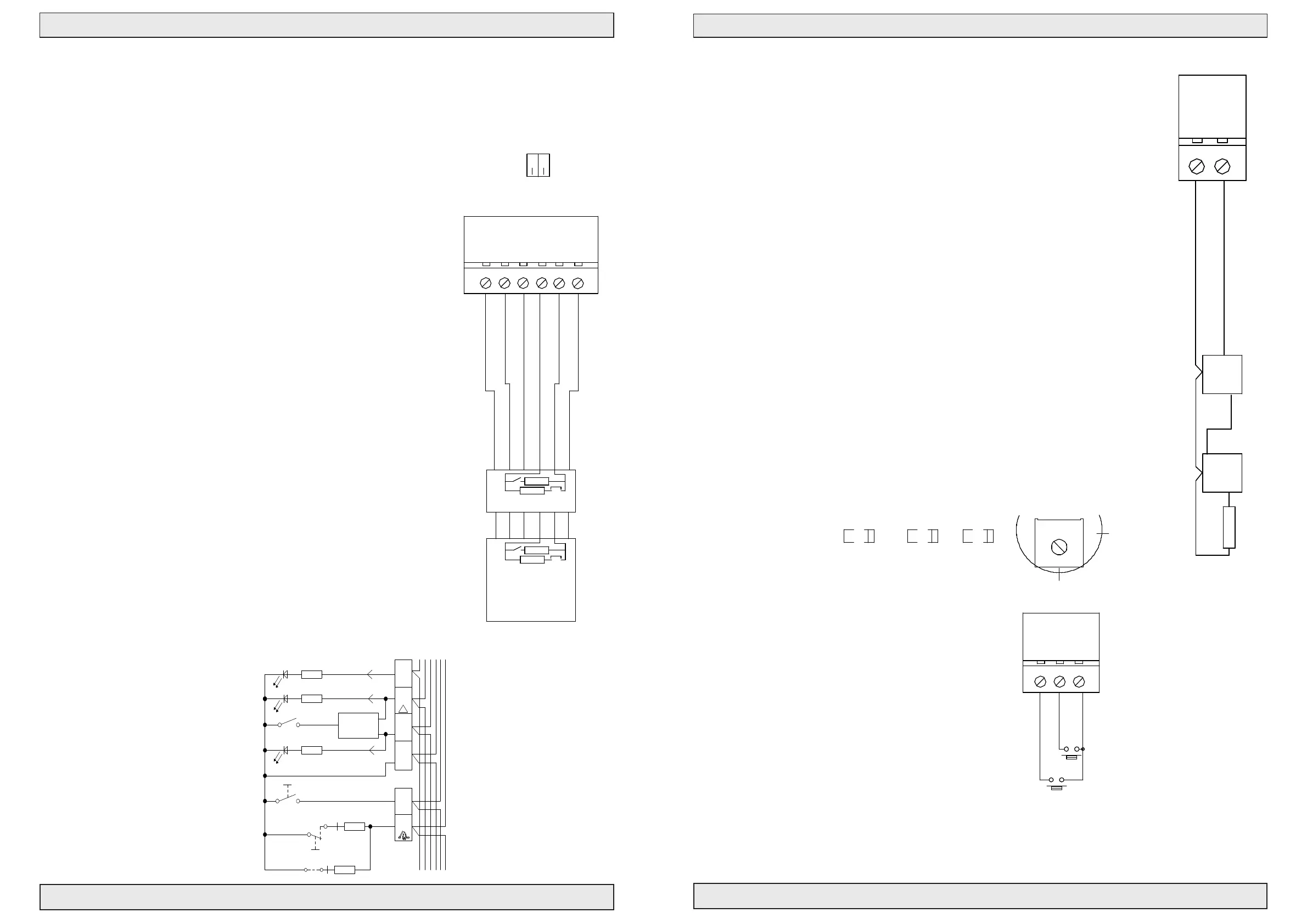
CONNECTION of the re switch is made as shown on the drawing.
The installation with re switches must be terminated with a 10KΩ or
27KΩ resistor in the last switch in order to establish the line monitoring
correctly – this can either be done by moving the factory mounted resistor
from the terminal strip to the last re switch or connect jumper J1 in
the re switch type BVT is mounted (by this a 10KΩ resistor is also
connected).
By means of DIP switches the control panel has different possibilities of
settings for the input to the re switch:
DIP 1 (Conf. resw.):
On = ALARM condition from 500-3KΩ, (indication of line error by direct
short circuit or open circuit).
Off = ALARM condition from 0-3KΩ (indication of line error by open
circuit).
DIP 2 (Failsafe):
On = Any line error on re switch or smoke detector puts the control panel
in ALARM condition. This function can be used if cables to re switches
and smoke detectors are not reproof.
Off = An error condition does not report ALARM condition.
BVT
Operation and connection of Manual Control Points
DIP NO
FAIL SAFE
OFF
Fail. 24V
ALARM
OK 24V
7
43
Fire switch type BVT
→
Con. Fire. Sw
BVT for line monitoring
2,2Ω
10 KΩ
4
3
2
1
J1
6
7
Fire switch BVT No. 1
Red LED
Yellow LED
Green LED
10 KΩ
2,2Ω
43
2
1
Gnd
11 12
24V
10 13
6
J1
7
6
FIRE
15
Reset
14
21
Fit J1 in last
2
1
ON
→
REV:
2 OF 4
Denmark
A4
SCALE:SHEET:
DWG NO.:
DRAWN BY: PSP
DATE: 26-09-17
TITLE:
DK 9560 Hadsund
Haandvaerkervej 2
1:1
211704_03
Actulux A/S
www.actulux.com
SIZE:
Phone int.: +45 98 57 40 90
Fax int.: +45 96 15 28 00
e-mail: info@actulux.com
ENGELSK
Ω
Ω
1 green LED OK (lights when OK and while closing)
2 yellow LED (lights on error)
3 red LED alarm (emergency opening)
4 ground (-)
5 not used
6 re switch reset
7 re switch emergency opening
Jumper J1 must only be set in the last or only re switch
Smoke- and heat detectors are connected as shown.
Line monitoring: Correct line monitoring can only be guaranteed with detectors
delivered from the supplier. Other detectors may have different internal resistances
and stand by power consumption.
Comfort ventilation – Connection and settings
The motor output can be controlled separately with a comfort switch.
For comfort ventilation there are the following possibilities:
Potentiometer in Puls pos.:
It is possible to press the »up« button 3 times, which each gives 6 seconds of opening
time - after that nothing happens – Continuous »up« signal gives 3x6 sec.=18 sec.
- One press on »down« closes the actuator completely for a period which is 18 sec.
longer than the complete opening time - In order to avoid »actuator pumping« max. 3
successive closing attempts will be allowed.
Potentiometer in Const. pos.:
As long as »up« signal or »down« signal are given, the actuators are running
Potentiometer in Puls variable pos.:
The time on the above mentioned pulse opening can be adjusted from 0-60 sec. on the
potentiometre.
When moving the potentiometer into the different positions the LED batt low will
ash for about 4 sec. to indicate when in puls mode. LED line fail ashes 4 sec. when
in constant and AC fail ashes when in puls varaiable.
Connection of smoke-/heat detectors
L1 Out
17
10 KΩ
Smoke or heat sensors
L1 Out
L2
Nr.2-20
L1 In
Gnd
16
L1 In
Nr.1
L2
Smoke
(Only last sensor)
A4
REV:
1:1
DWG NO.:
Denmark
SHEET: DRAWN BY: PSP
DATE: 26-09-17
TITLE:
SCALE:
DK 9560 Hadsund
Haandvaerkervej 2
211704_04
Actulux A/S
www.actulux.com
SIZE:
2 OF 3
Phone int.: +45 98 57 40 90
Fax int.: +45 96 15 28 00
e-mail: info@actulux.com
ENGELSK/TYSK
20
Gnd
18
Up
19
Down
Up
Down
P
u
l
s
v
a
r
i
a
b
l
e
Min
C
o
n
s
t
.
Potmeter for
comfort feature
Max.
Puls
YELYEL YEL
AC FAIL LINE FAIL BATT LOW
Actulux A/S
211704_05
1:1
1 OF 2
SCALE:
DWG NO.:
Denmark
DRAWN BY: PSP
DATE: 26-09-17
TITLE:
DK 9560 Hadsund
Haandvaerkervej 2
www.actulux.com
SIZE: SHEET:
REV:
A4
Phone int.: +45 98 57 40 90
Fax int.: +45 96 15 28 00
e-mail: info@actulux.com
DANSK/ENGELSK/TYSK
Room thermostats, weekly timers, CCS and
other external control equipment for comfort
ventilation can be connected on the input of the
comfort control.
 Loading...