12
13
Control for Fire and Comfort Ventilation Type SVM 24V-5A / SVM 24V-8A
Control for Fire and Comfort Ventilation Type SVM 24V-5A / SVM 24V-8A
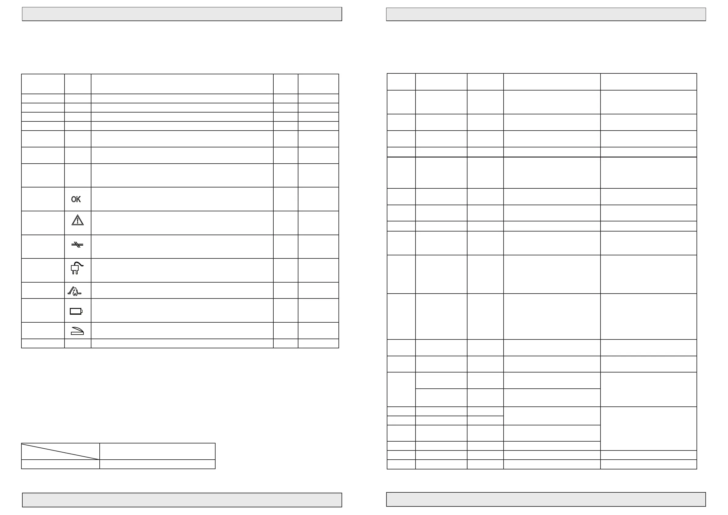
LED/colour Symbol Operation possibilities for: Alarm/
re
Comfort
operation
LD1/red Actuator open (red). Lights when actuator opens
LD2/green Actuator close (green). Lights when actuator closes
LD3/red Weather sensor active (red). Lights when weather sensor is active Yes No
LD4/red Line error on actuator (red). Lights when actuator has line error Yes Only close
LD5/red Line error on re switch (red). Lights when re switch has line error,
ashes when SVM Add-on has line error.
Yes Only close
LD6/red Line error on smoke detector (red). Lights when smoke detector has
line error, ashes at temperatures above 75°
Yes Only close
LD7/red Bus error (red). Lights when BUS signal from other controls
is missing. Only relevant if J24 or J25 is mounted. Flashes if
connection to Add-on PCB is missing
Yes Only close
Green
Board + Front
lights if everything is ok
switched off by local error on this control
ashes by error message from other controls received by bus
Yes Yes
Yellow
Board + Front
Fault
lights by local error on this control
or by error message from other controls received by bus
Yes Only close
*Yellow
Board + Front
Line error
ashes by local error on this control
or by error message from other controls received by bus
Yes Only close
*Yellow
Board + Front
AC error
ashes by local error on this control
or by error message from other controls received by bus
Yes Only close
Red
Board + Front
Alarm
lights red constantly
Yes No
*Yellow
Board + Front
DC error
ashes by local battery error on this control
or by error message from other controls received by bus
Blue
Board + Front
Lights blue constantly in open condition (when windows are open)
ashes when actuator is moving up and down
Lights with* Time for yearly service - please call for supplier (ashes fast) Yes Yes
Fuse specications
Placement
Fuse value
24V
F1 8A fast ading fuse
1 pc. for 24V motor output
Text on board Factory
mounted
Mounted / ON function Dismounted / OFF function
DIP 1 Conf. Fireswitch No Fire switch active from 500-3KΩ.
A short circuit of the smoke detector
input will generate a line error
Fire switch active from 0-3KΩ.
A short circuit of the smoke detector
input will generate alarm
DIP 2 Failsafe No Line error on re switch or detector
puts the control in alarm
Normal mode
DIP 3 Temp. Detekt No Line error on motor line
(upper resistor area) = alarm
Normal mode
DIP 4 Ser Yes Active Inactive
DIP 5 Snitch No LED’s “remember” errors (line
errors, AC/Batt. error, bus error). The
LED’s can only be switched off/reset
again by setting dip switch off
Normal mode
DIP 6 Fail Relay No Failure relay works as indication that
skylight is open
Normal mode (works as failure
relay)
DIP 7 Week open No Weekly open (2 sec.) /close
(5 sec.) cycle activated
Weekly open/close not activated
DIP 8 AG Mode special No Special “Fire close” button enabled Normal mode
DIP 9 Sprinkler No Motor output closes by active
detector (opens by activating the re
switch)
Normal mode - motor output opens
by ative detectors or re switches
DIP 10 Bus comfort No The control reacts on comfort signal
via bus activity
The control does not react on
comfort signals via bus activity //
NB! Always reaction on weather
signal and failures via bus activity
and own comfort signal
DIP 11 Bus re No The control reacts on alarm signal
via bus activity
The control does not react on alarm
signal via bus activity
//NB! Always reaction on weather
signal and failures via bus activity
and own alarm signal (detector or
re switch)
DIP 12 BRA Mode special No Special re switch/alarm mode and
comf. active at all failures
Normal mode
J3
(motor)
1 - 2 - 3 - 4 Pos. 1 Connect according to number of
27KΩ terminal resistors on actuator
No line monitoring
J2
(motor)
Mot Mon act. Ye s 2 wire line monitoring via 27KΩ
terminal 2-3
No line monitoring
Ext Li Mon act. No 3 wire line monitoring with direct
motor connection actuator
J4(Bus) Start term. No
First control panel in the bus network
See section concerning connection
of controls panels in bus connection,
page 14
J5(Bus) + Master No
J6(Bus) Slave No Middle and last control panel in the
bus network
J7(Bus) End term. No Last control panel in the bus network
J9 FOIL Yes in Basic Line monotoring of front cabinet Line error ashes
J11 BatSup->Ø23 No Battery backup of terminal 23 Terminal 23 only AC supplied
Others: Reset time = 180 sec. closing // Cut-off motor output and loading after 360 sec. // Comf. var (potetiometer): 1-60 sec.
Complete jumper settings
LEDs on main board and front panel
 Loading...