6
7
Control for Fire and Comfort Ventilation Type SVM EI 24V-5A / SVM EI 24V-8A
Control for Fire and Comfort Ventilation Type SVM EI 24V-5A / SVM EI 24V-8A
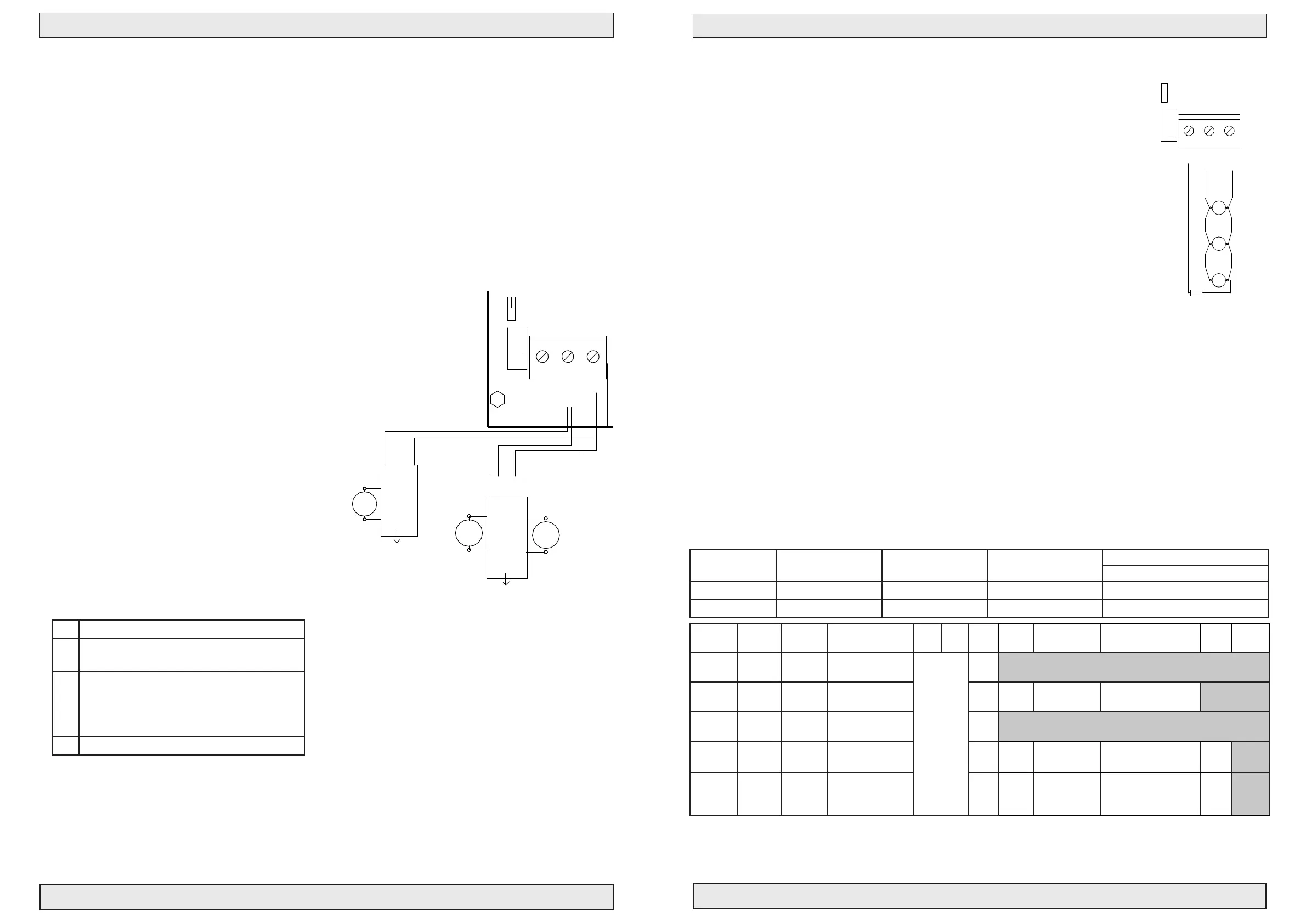
Jumper J2 mounted in pos. »Motor line«
Line monitoring between terminal 2-3.
Jumper J3 (actuator output) is set according to
the number of termination resistors (27 KΩ) to
be detected – 1 to max. 4 lines can be detected
by moving jumper J3 – this means that the cable
installation between the control panel and the
actuators can be established in series connection
(cable connection from e.g. skylight 1, further
to skylight 2, etc.), or parallel connection (cable
connection from each skylight to the control), or
a combination of these. However, as mentioned
max. 4 different lines can be detected each
terminated with a 27 KΩ resistor.
For SVM EI 24V-5A:
the max. allowed current is 5A.
For SVM EI 24V-8A:
the max. allowed current is 8A.
Jumper description
J3
Number of connected 27Kohm terminal
resistors for actuator output
J2
Chooses line monitoring through motor
terminals 2-3 (Mot Mon) or separate
wire terminals 1-3 (Ext Li Mon), or no
line monitoring when J2/J3 is removed
F1
Fuse 8A for actuator output
PriorWeather
J11
K11
#111961
AWR-24
24V
®
2,2KΩ
Blue
1 Cannel LIP 7
M2
12
5
6
LIP #2
M1
8
7
34
Brown
2 channel LIP 6
Next LIP
Brown
Blue
Next LIP
Max. Torque 0.5 Nm
Max. Torque 0.5 Nm
Open
24
Close
25 27
Gnd
NO FOIL
26
Keyboard
T
OpenLed
RESET
NO
NC
COM
AC/DC
B4
A4
RED
GRE
#111960
RED
RED
RED
RED
RED
®
Manuel Control Point Smoke Comfort
R
E
S
E
#111980
See page 12
}
RED
ALARM
GRE
OK
YEL
FAILURE
J8
BUZZER ON/OFF
RED
RED
RED
RED
RED
GRE
RED
LED 1 Actuator open (red). Lit when actuator is opening.
LED 2 Actuator closing (green). Lit when actuator is closing.
LED 3 Weather sensor active (red). Lit when weather sensor is active.
LED 4 Line failure actuator (red). Lit for line failure on actuator.
LED 5 Line failure fire switch (red). Lit for line failure on fire switch.
LED 6 Line failure smokesensor (red). Lit for line fail. on smokes.
LED 7 BUS failure (red). Lit when local unit is not recieving signal.
LOCKOUT
TEMP DETECT
SERVICE TIMER
SNITCH
FAIL RELAY M.
WEEK OPEN
OPTION
SPRINKLER
BUS COMFORT
BUS FIRE
12
3
4
6
7
5
8
11
9
10
BUS Master
BUS Slave
END termination
Puls
Max.
Potmeter for
comfort features
Con. Fire. Sig
FAIL SAFE
Min
Co
n
s
t
.
BATT LOW
P
u
l
s
v
a
r
i
a
b
l
e
YEL
LINE FAILAC FAIL
YEL YEL
BAT +
BAT -
ON
®
DIP NO.
1
2
OFF
®
START termination
DOME OPEN
BLUE
PS +
PS -
-
+
+
Black 2,5mm2
-
- 24VDC +
Batteries 2x 12V - 7,2 Ah
24V Red 2,5mm2
Connection
SVM EI 24V - 5A/8A
BUZZER
B3
®
J5
J6
J7
A3
B1 B2
®
®
Serial Out
next unit.
Connection to
®
A1
prev. unit.
®
2120
Gnd
2322
Weather
Gnd
24V
A2
Serial In
Connection from
Bus connection for serial connection
up to 35 pcs. control units.
®
J4
Set J11 for batteri backup
of terminal 23
18
Up
17
Smoke
16
Gnd
19
Down
13
24V
ALARM
Fail. 24V
1211
FIRE
Gnd
15
Reset
14
COM
7
NO
NC
98
Failure OutAlarm Out
NC
5
COM
4
NO
6
3
OK 24V
10
L1 Out
L1 In
No.1
L2
L1 In
L2
Up
2,2KΩ
Fire switch BVT No. 1
10 KΩ
1 32 6 74
J1
Red LED
Yellow LED
Green LED
Extra relay print #111933
provides 2 additional
potential free contacts
each 30V 0,5A
Potential free ALARM switch.
Com + NO connected on alarm.
Max 48V 0,5A
Potential free Failure switch.
Com + NO connected on failure.
Max 48V 0,5A
heat sensors
Smoke or
Down
(Close all)
10 KΩ
L1 Out
Comfort
1
2
3
4
7
6
10 KΩ
J1
Fire switch type BVT.
Fit J1 in last BVT for
line monitoring
(only last sensor)
Connection diagram SVM EI 24
Drawing: 211863_B
1 23 4
7
6
Nr.2-20
Switch
Wind and rain sensor
Max. 8A
FUSE F1 - fast
J 34
J2
12
Line 1
1
2
N1
3
13 A Autofuse
PE L1
1
Blue
2
M1
Brown
1
2
6
LIP #1
5
Actuator
Motor line monitor
Ext 3 wire monitor (line 1)
24V Out
PS1
Power Supply 180-250 VAC
24VDC 150W/200W
NTC
J9
Without keyboard jumper mounted
J1
DIP settings see page 13
REMOTE
no: 111894
GND
LED
OPEN
CLOSE
61
Firemans Priority switch
OPENCLOSE
Jumper J2 in pos. »Ext 3 wire«.
Line monitoring between terminal 1-3:
With jumper J3 (actuator output) it is chosen, how many lines (number of 27 KΩ)
you wish to detect - the same way as the motor line.
This setting demands 3 wire cable from motor output to motor.
Current limiter type LIP function and setting (if mounted)
The current limiter type LIP (mounted on the opening system) is used as current limiter between the
24V/48VDC supply and 1 or 2 actuators. When the adjusted current limit is reached, the speed of the
actuators is reduced. When the max. power on the actuator is exceeded, the actuator stops. On the
24V /48V types (LIP5, LIP6 or LIP7) max. 3 times overload cut outs in the same direction is allowed.
After that it will not be possible to run in this direction again, before the motor has run in the opposite
direction. This in order to protect the actuator gear mechanism.
Please note that when opening, the red LED in the LIP must light. This indicates that polarity to
actuator is correct.
M1M2Mn
27K Ohm
(Only last
actuator)
J3
J2
4
3
2
Actuator
Motor line monitor
Ext 3 wire monitor (line 1)
3
-
Line 1
12
+
1
24V Out
Actuator
+
+
A4
REV:
SHEET:
Denmark
SCALE:
2 OF 3
DWG NO.:
DRAWN BY: PSP
DATE: 26-09-17
TITLE:
DK 9560 Hadsund
Haandvaerkervej 2
1:1
211704_02
Actulux A/S
www.actulux.com
SIZE:
Phone int.: +45 98 57 40 90
Fax int.: +45 96 15 28 00
e-mail: info@actulux.com
ENGELSK/TYSK
Connection to motor- (actuator-) output and line monitoring
The actuators (motors) must be connected to the actuator output on the output terminals 2-3.
It is possible to connect and disconnect the line monitoring on the actuator output (the factory setting is
“connected”). The cables to the actuators can be connected in series or parallel or a combination of these
(please see drawing with examples or connection diagram on the mid pages).
It is important to keep the right polarity of the cables - The actuators must always be connected through a
current limiter, e.g. the Actulux LIP or similar.
Cable monitoring (line monitoring) on the motor output
The control is equipped with 3 possible settings for cable
monitoring (line monitoring), which can be congured by
means of jumper J2.
* SA Power Large - parallel operation: Jumper OPT mounted - both motors stop at the same time if one stops because of overload.
** When DIP4 is OFF = Tandem mode - both motors stop at the same time if no current ows in one. (1.5 sec. reaction time)
*** Requires actuator with Reed. (3-core incl. black cable)
**** OFF = No delay between Master og Slave / ON = Seven sec. delay between Master and Slave.
Table of LIP settings
Opening System
24V/48V
3A/1.5A SA Power
Single, Double, Large
4A/2A SA Power
Single, Double, Large
2.5A/1.25A SA Power
Mini
2.5A/1.25A Rotary 100 LIP5/6
2A/1A SA Power Mini LIP7
DIP 1 ON OFF ON OFF
DIP 2 OFF ON ON OFF
Type Board
no.
Board
descrip.
Voltage and
function
DIP
1
DIP
2
DIP
3
DIP
4
DIP
5
DIP
6
DIP
7
DIP
8
LIP5 121315 A043 24/48V
1 channel
See
diagram
above
27K
ON
Not mounted
LIP6 * 121330 A044 24/48V
2 channels
OFF ON** 27K ON M1-M2 delay =ON
LIP7
Basic
121305 LIP7 24/48V
1 channel
27K
ON
Not mounted
LIP7
TA
121306 LIP7 24/48V 1 channel
Tandem
27K
ON
ON =
Com
OFF = Slave
ON = Master
OFF = Syncro Mode
ON = Tandem Mode
****
Not in
use
LIP7***
OC
121308 LIP7 24/48V
1 channel Syncro
m/position ind.
27K
ON
ON =
Com
OFF = Slave
ON = Master
OFF = Syncro Mode
ON = Tandem Mode ****
Not in
use
No line monitoring
To disable line monitoring, place the 27KΩ resistor in terminal 1 and 3.
Set J2 to “Ext 3 wire monitor (line 1)”, and set J3 to “1”.
Now use Actuator out on 2 and 3.
NOTE: it is recommended that line monitoring should always be activated wherever
possible
LED 4 indicates if there is any fail on the actuator output. Steady light if wire is broken.
“Flashing fast” in case output is connected to earth. Flashing slow if output is shorted.
NOTE: When Flashing RESET or close is not possible
 Loading...