8
9
Control for Fire and Comfort Ventilation Type SVM EI 24V-5A / SVM EI 24V-8A
Control for Fire and Comfort Ventilation Type SVM EI 24V-5A / SVM EI 24V-8A
The Manual Control Point will generally contain the following:
• Breakable glass window and red control button is activated by
pressure - this puts the control panel in ALARM condition, by
which the motor output is activated (for normal service and testing
the lid can be opened with a key).
• RESET button which brings the control panel out of the alarm
condition and starts the closing sequence for about 180 seconds.
Please note that RESET does not cancel errors on the system, e.g.
line errors etc. These must be found and corrected.
• RED LED indicates that the control panel is in ALARM condition
and that the motor output either is or has been activated.
• YELLOW LED indicates faults on the system - please call for a
service technician.
• GREEN LED indicates that the system is in normal operation
condition without errors.
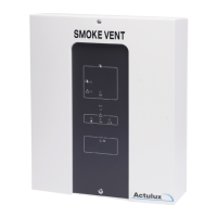
CONNECTION of the re switch is made as shown on the drawing.
The installation with re switches must be terminated with a 10 KΩ or
27 KΩ resistor in the last switch in order to establish the line monitoring
correctly – this can either be done by moving the factory mounted resistor
from the terminal strip to the last re switch or connect jumper J1 in
the re switch type BVT is mounted (by this a 10 KΩ resistor is also
connected).
By means of DIP switches the control panel has different possibilities of
settings for the input to the re switch:
DIP 1 (Conf. resw.):
On = ALARM condition from 500-3 KΩ, (indication of line error by direct
short circuit or open circuit).
Off = ALARM condition from 0-3 KΩ (indication of line error by open
circuit).
DIP 2 (Failsafe):
On = Any line error on re switch or smoke detector puts the control panel
in ALARM condition. This function can be used if cables to re switches
and smoke detectors are not reproof.
Off = An error condition does not report ALARM condition.
BVT
Operation and connection of Manual Control Points
DIP NO
FAIL SAFE
OFF
→
Con. Fire. Sw
BVT for line monitoring
2,2Ω
10 KΩ
4
3
2
1
J1
6
7
Fire switch BVT No. 1
Red LED
Yellow LED
Green LED
10 KΩ
2,2Ω
43
2
1
Gnd
11 12
24V
10 13
6
J1
7
6
FIRE
15
Reset
14
21
ON
→
REV:
2 OF 4
Denmark
A4
SCALE:SHEET:
DWG NO.:
DRAWN BY: PSP
DATE: 26-09-17
TITLE:
DK 9560 Hadsund
Haandvaerkervej 2
1:1
211704_03
Actulux A/S
www.actulux.com
SIZE:
Phone int.: +45 98 57 40 90
Fax int.: +45 96 15 28 00
e-mail: info@actulux.com
ENGELSK
Denmark
111700 B
SIZE:
www.actulux.com
DWG NO.:
DRAWN BY: PSP
DATE: 07-02-17
TITLE:
SCALE:
DK 9560 Hadsund
Haandvaerkervej 2
REV:
A4 1 OF 2
2:1
Diagram BVT fireswitch
SHEET:
Actulux A/S Phone int.: +45 98 57 40 90
Fax int.: +45 96 15 28 00
e-mail: info@actulux.com
111693 Fireswitch 111784
Reset
Alarm
2
4
10 KΩ
3
OK
24V
LED
LED
Reset
7
Buzzer
2,2 KΩ
GND
6
J1
Buzzer
24V
Jumper
Alarm
1
LED
24V
Rød/Red
Rot/Rouge
Gul/Yellow
Gelb/Jaune
Grøn/Green
Grün/Vert
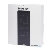
1 green LED OK (lights when OK and while closing)
2 yellow LED (lights on error)
3 red LED alarm (emergency opening)
4 ground (-)
5 not used
6 re switch reset
7 re switch emergency opening
Jumper J1 must only be set in the last or only re switch
Smoke- and heat detectors are connected as shown.
Line monitoring: Correct line monitoring can only be guaranteed with detectors
delivered from the supplier. Other detectors may have different internal resistances
and stand by power consumption.
Comfort ventilation – Connection and settings
The motor output can be controlled separately with a comfort switch.
For comfort ventilation there are the following possibilities:
Potentiometer in Puls pos.:
It is possible to press the »up« button 3 times, which each gives 6 seconds of opening
time - after that nothing happens – Continuous »up« signal gives 3x6 sec.=18 sec.
- One press on »down« closes the actuator completely for a period which is 18 sec.
longer than the complete opening time - In order to avoid »actuator pumping« max. 3
successive closing attempts will be allowed.
Potentiometer in Const. pos.:
As long as »up« signal or »down« signal are given, the actuators are running
Potentiometer in Puls variable pos.:
The time on the above mentioned pulse opening can be adjusted from 0-60 sec. on the
potentiometre.
When moving the potentiometer into the different positions the LED batt low will
ash for about 4 sec. to indicate when in puls mode. LED line fail ashes 4 sec. when
in constant and AC fail ashes when in puls varaiable.
Connection of smoke-/heat detectors
PriorWeather
J11
K11
#111961
AWR-24
24V
®
2,2KΩ
Blue
1 Cannel LIP 7
M2
12
5
6
LIP #2
M1
8
7
34
Brown
2 channel LIP 6
Next LIP
Brown
Blue
Next LIP
Max. Torque 0.5 Nm
Max. Torque 0.5 Nm
Open
24
Close
25 27
Gnd
NO FOIL
26
Keyboard
T
OpenLed
RESET
NO
NC
COM
AC/DC
B4
A4
RED
GRE
#111960
RED
RED
RED
RED
RED
®
Manuel Control Point Smoke Comfort
R
E
S
E
#111980
See page 12
}
RED
ALARM
GRE
OK
YEL
FAILURE
J8
BUZZER ON/OFF
RED
RED
RED
RED
RED
GRE
RED
LED 1 Actuator open (red). Lit when actuator is opening.
LED 2 Actuator closing (green). Lit when actuator is closing.
LED 3 Weather sensor active (red). Lit when weather sensor is active.
LED 4 Line failure actuator (red). Lit for line failure on actuator.
LED 5 Line failure fire switch (red). Lit for line failure on fire switch.
LED 6 Line failure smokesensor (red). Lit for line fail. on smokes.
LED 7 BUS failure (red). Lit when local unit is not recieving signal.
LOCKOUT
TEMP DETECT
SERVICE TIMER
SNITCH
FAIL RELAY M.
WEEK OPEN
OPTION
SPRINKLER
BUS COMFORT
BUS FIRE
12
3
4
6
7
5
8
11
9
10
BUS Master
BUS Slave
END termination
Puls
Max.
Potmeter for
comfort features
Con. Fire. Sig
FAIL SAFE
Min
Co
n
s
t
.
BATT LOW
P
u
l
s
v
a
r
i
a
b
l
e
YEL
LINE FAILAC FAIL
YEL YEL
BAT +
BAT -
ON
®
DIP NO.
1
2
OFF
®
START termination
DOME OPEN
BLUE
PS +
PS -
-
+
+
Black 2,5mm2
-
- 24VDC +
Batteries 2x 12V - 7,2 Ah
24V Red 2,5mm2
Connection
SVM EI 24V - 5A/8A
BUZZER
B3
®
J5
J6
J7
A3
B1 B2
®
®
Serial Out
next unit.
Connection to
®
A1
prev. unit.
®
2120
Gnd
2322
Weather
Gnd
24V
A2
Serial In
Connection from
Bus connection for serial connection
up to 35 pcs. control units.
®
J4
Set J11 for batteri backup
of terminal 23
18
17
Smoke
16
Gnd
19
Down
13
24V
ALARM
Fail. 24V
1211
FIRE
Gnd
15
Reset
14
COM
7
NO
NC
98
Failure OutAlarm Out
NC
5
COM
4
NO
6
3
OK 24V
10
L1 Out
L1 In
No.1
L2
L1 In
L2
Up
2,2KΩ
Fire switch BVT No. 1
10 KΩ
1 32 6 74
J1
Red LED
Yellow LED
Green LED
Extra relay print #111933
provides 2 additional
potential free contacts
each 30V 0,5A
Potential free ALARM switch.
Com + NO connected on alarm.
Max 48V 0,5A
Potential free Failure switch.
Com + NO connected on failure.
Max 48V 0,5A
heat sensors
Smoke or
10 KΩ
L1 Out
Comfort
1
2
3
4
7
6
10 KΩ
J1
Fire switch type BVT.
Fit J1 in last BVT for
line monitoring
(only last sensor)
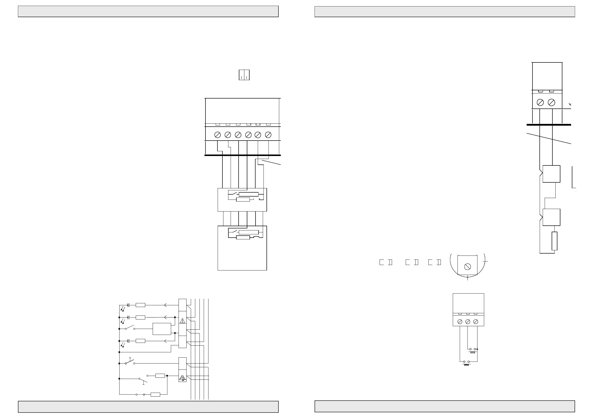
Connection diagram SVM EI 24
Drawing: 211863_B
1 23 4
7
6
Nr.2-20
Switch
Wind and rain sensor
Max. 8A
FUSE F1 - fast
J 34
J2
12
Line 1
1
2
N1
3
13 A Autofuse
PE L1
1
Blue
2
M1
Brown
1
2
6
LIP #1
5
Actuator
Actuator
Motor line monitor
Ext 3 wire monitor (line 1)
24V Out
PS1
Power Supply 180-250 VAC
24VDC 150W/200W
NTC
J9
Without keyboard jumper mounted
J1
DIP settings see page 13
REMOTE
no: 111894
GND
LED
OPEN
CLOSE
61
Firemans Priority switch
OPENCLOSE
20
Gnd
18
Up
19
Down
Up
Down
Comfort
Switch Ch 1
P
u
l
s
v
a
r
i
a
b
l
e
Min
C
o
n
s
t
.
Potmeter for
comfort feature
Max.
Puls
YELYEL YEL
AC FAIL LINE FAIL BATT LOW
Actulux A/S
211704_05
1:1
1 OF 2
SCALE:
DWG NO.:
Denmark
DRAWN BY: PSP
DATE: 26-09-17
TITLE:
DK 9560 Hadsund
Haandvaerkervej 2
www.actulux.com
SIZE: SHEET:
REV:
A4
Phone int.: +45 98 57 40 90
Fax int.: +45 96 15 28 00
e-mail: info@actulux.com
DANSK/ENGELSK/TYSK
Room thermostats, weekly timers, CCS and
other external control equipment for comfort
ventilation can be connected on the input of the
comfort control.
PriorWeather
J11
K11
#111961
AWR-24
24V
®
2,2KΩ
Blue
1 Cannel LIP 7
M2
12
5
6
LIP #2
M1
8
7
34
Brown
2 channel LIP 6
Next LIP
Brown
Blue
Next LIP
Max. Torque 0.5 Nm
Max. Torque 0.5 Nm
Open
24
Close
25 27
Gnd
NO FOIL
26
Keyboard
T
OpenLed
RESET
NO
NC
COM
AC/DC
B4
A4
RED
GRE
#111960
RED
RED
RED
RED
RED
®
Manuel Control Point Smoke Comfort
R
E
S
E
#111980
See page 12
}
RED
ALARM
GRE
OK
YEL
FAILURE
J8
BUZZER ON/OFF
RED
RED
RED
RED
RED
GRE
RED
LED 1 Actuator open (red). Lit when actuator is opening.
LED 2 Actuator closing (green). Lit when actuator is closing.
LED 3 Weather sensor active (red). Lit when weather sensor is active.
LED 4 Line failure actuator (red). Lit for line failure on actuator.
LED 5 Line failure fire switch (red). Lit for line failure on fire switch.
LED 6 Line failure smokesensor (red). Lit for line fail. on smokes.
LED 7 BUS failure (red). Lit when local unit is not recieving signal.
LOCKOUT
TEMP DETECT
SERVICE TIMER
SNITCH
FAIL RELAY M.
WEEK OPEN
OPTION
SPRINKLER
BUS COMFORT
BUS FIRE
12
3
4
6
7
5
8
11
9
10
BUS Master
BUS Slave
END termination
Puls
Max.
Potmeter for
comfort features
Con. Fire. Sig
FAIL SAFE
Min
Co
n
s
t
.
BATT LOW
P
u
l
s
v
a
r
i
a
b
l
e
YEL
LINE FAILAC FAIL
YEL YEL
BAT +
BAT -
ON
®
DIP NO.
1
2
OFF
®
START termination
DOME OPEN
BLUE
PS +
PS -
-
+
+
Black 2,5mm2
-
- 24VDC +
Batteries 2x 12V - 7,2 Ah
24V Red 2,5mm2
Connection
SVM EI 24V - 5A/8A
BUZZER
B3
®
J5
J6
J7
A3
B1 B2
®
®
Serial Out
next unit.
Connection to
®
A1
prev. unit.
®
2120
Gnd
2322
Weather
Gnd
24V
A2
Serial In
Connection from
Bus connection for serial connection
up to 35 pcs. control units.
®
J4
Set J11 for batteri backup
of terminal 23
18
Up
17
Smoke
16
Gnd
19
Down
13
24V
ALARM
Fail. 24V
1211
FIRE
Gnd
15
Reset
14
COM
7
NO
NC
98
Failure OutAlarm Out
NC
5
COM
4
NO
6
3
OK 24V
10
L1 Out
L1 In
No.1
L2
L1 In
L2
Up
2,2KΩ
Fire switch BVT No. 1
10 KΩ
1 32 6 74
J1
Red LED
Yellow LED
Green LED
Extra relay print #111933
provides 2 additional
potential free contacts
each 30V 0,5A
Potential free ALARM switch.
Com + NO connected on alarm.
Max 48V 0,5A
Potential free Failure switch.
Com + NO connected on failure.
Max 48V 0,5A
heat sensors
Smoke or
Down
(Close all)
10 KΩ
L1 Out
Comfort
1
2
3
4
7
6
10 KΩ
J1
Fire switch type BVT.
Fit J1 in last BVT for
line monitoring
(only last sensor)
Connection diagram SVM EI 24
Drawing: 211863_B
1 23 4
7
6
Nr.2-20
Switch
Wind and rain sensor
Max. 8A
FUSE F1 - fast
J 34
J2
12
Line 1
1
2
N1
3
13 A Autofuse
PE L1
1
Blue
2
M1
Brown
1
2
6
LIP #1
5
Actuator
Actuator
Motor line monitor
Ext 3 wire monitor (line 1)
24V Out
PS1
Power Supply 180-250 VAC
24VDC 150W/200W
NTC
J9
Without keyboard jumper mounted
J1
DIP settings see page 13
REMOTE
no: 111894
GND
LED
OPEN
CLOSE
61
Firemans Priority switch
OPENCLOSE
Auto reset
When setting OPTION(DIP8) On, an automatic reset is performed 2 seconds after the re signal is
removed. (From software version V1.005)
 Loading...