16
17
Control for Fire and Comfort Ventilation Type SVM EI 24V-5A / SVM EI 24V-8A
Control for Fire and Comfort Ventilation Type SVM EI 24V-5A / SVM EI 24V-8A
Special functions
Sprinkler function:
DIP 9 On - a special function comes in use where sprinkler systems are installed. With this function
activated, the actuator output closes, if smoke-/heat detector input is activated.
If the re switch is activated, the actuator output opens.
Weekly open/close:
DIP 7 On - the motor output opens shortly (3 seconds) once a week and closes immediately after -
This function is used to give the right tension on the packing of the skylights to keep them watertight.
Function of heat detector in LIP:
DIP 3 On - a heat detector 70-100 °C can be mounted in each LIP. If the temperatur is exceeded, the
control panel goes into alarm and the opening system is opening.
Lock-Out Mode:
DIP 12 On - see page 18
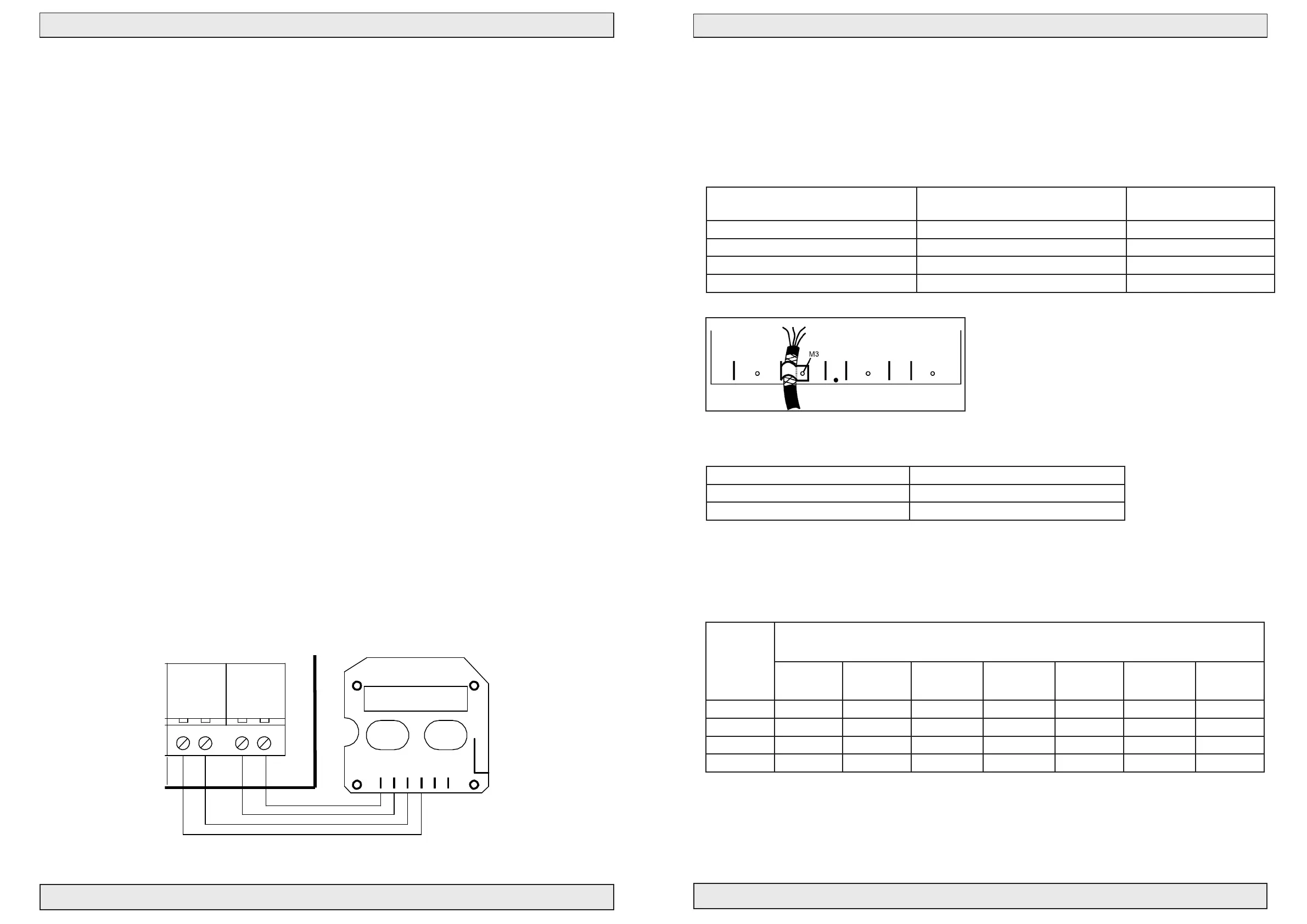
Fireman’s Priority Switch
The Fireman’s Priority switch is an override switch, which makes it possible for the Fireman to control the
panel regardless of sensor inputs.
Connection/function
- The CLOSE-switch activates the panel in close condition for 180 seconds, and the panel stays in re mode.
- The OPEN-switch activates the panel in open condition if not in re mode, and the panel enters re mode.
- The LED output is activated in open condition (windows are open).
When actuator is moving up or down LED ashes with 1Hz, in case of fail LED ashes with 10 Hz.
- The output is maximum 1 mA 24V.
- OPEN and CLOSE switches have line surveillance.
- Only one Fireman’s Priority Switch can be connected.
- When activating OPEN and CLOSE at the same time = reset is performed.
- The input is not a part of Congure Fire switch DIP1 = the input is active between 0-3 Kohm.
Prior
Weather
J11
K11
#111961
AWR-24
24V
®
2,2KΩ
Blue
1 Cannel LIP 7
M2
12
5
6
LIP #2
M1
8
7
34
Brown
2 channel LIP 6
Next LIP
Brown
Blue
Next LIP
Max. Torque 0.5 Nm
Max. Torque 0.5 Nm
Open
24
Close
25 27
Gnd
26
T
OpenLed
RESET
NO
NC
COM
AC/DC
B4
A4
RED
GRE
#111960
RED
RED
RED
RED
RED
®
Manuel Control Point Smoke Comfort
R
E
S
E
#111980
See page 12
}
RED
ALARM
GRE
OK
YEL
FAILURE
J8
BUZZER ON/OFF
RED
RED
RED
RED
RED
GRE
RED
LED 1 Actuator open (red). Lit when actuator is opening.
LED 2 Actuator closing (green). Lit when actuator is closing.
LED 3 Weather sensor active (red). Lit when weather sensor is active.
LED 4 Line failure actuator (red). Lit for line failure on actuator.
LED 5 Line failure fire switch (red). Lit for line failure on fire switch.
LED 6 Line failure smokesensor (red). Lit for line fail. on smokes.
LED 7 BUS failure (red). Lit when local unit is not recieving signal.
LOCKOUT
TEMP DETECT
SERVICE TIMER
SNITCH
FAIL RELAY M.
WEEK OPEN
OPTION
SPRINKLER
BUS COMFORT
BUS FIRE
12
3
4
6
7
5
8
11
9
10
BUS Master
BUS Slave
END termination
Puls
Max.
Potmeter for
comfort features
Con. Fire. Sig
FAIL SAFE
Min
Co
n
s
t
.
BATT LOW
P
u
l
s
v
a
r
i
a
b
l
e
YEL
LINE FAILAC FAIL
YEL YEL
BAT +
BAT -
ON
®
DIP NO.
1
2
OFF
®
START termination
DOME OPEN
BLUE
PS +
PS -
-
+
+
Black 2,5mm2
-
- 24VDC +
Batteries 2x 12V - 7,2 Ah
24V Red 2,5mm2
Connection
SVM EI 24V - 5A/8A
BUZZER
B3
®
J5
J6
J7
A3
B1 B2
®
®
Serial Out
next unit.
Connection to
®
A1
prev. unit.
®
2120
Gnd
2322
Weather
Gnd
24V
A2
Serial In
Connection from
Bus connection for serial connection
up to 35 pcs. control units.
®
J4
Set J11 for batteri backup
of terminal 23
18
Up
17
Smoke
16
Gnd
19
Down
13
24V
ALARM
Fail. 24V
1211
FIRE
Gnd
15
Reset
14
COM
7
NO
NC
98
Failure OutAlarm Out
NC
5
COM
4
NO
6
3
OK 24V
10
L1 Out
L1 In
No.1
L2
L1 In
L2
Up
2,2KΩ
Fire switch BVT No. 1
10 KΩ
1 32 6 74
J1
Red LED
Yellow LED
Green LED
Extra relay print #111933
provides 2 additional
potential free contacts
each 30V 0,5A
Potential free ALARM switch.
Com + NO connected on alarm.
Max 48V 0,5A
Potential free Failure switch.
Com + NO connected on failure.
Max 48V 0,5A
heat sensors
Smoke or
Down
(Close all)
10 KΩ
L1 Out
Comfort
1
2
3
4
7
6
10 KΩ
J1
Fire switch type BVT.
Fit J1 in last BVT for
line monitoring
(only last sensor)
Connection diagram SVM EI 24
Drawing: 211863_B
1 23 4
7
6
Nr.2-20
Switch
Wind and rain sensor
Max. 8A
FUSE F1 - fast
J 34
J2
12
Line 1
1
2
N1
3
13 A Autofuse
PE L1
1
Blue
2
M1
Brown
1
2
6
LIP #1
5
Actuator
Actuator
Motor line monitor
Ext 3 wire monitor (line 1)
24V Out
PS1
Power Supply 180-250 VAC
24VDC 150W/200W
NTC
J9
Without keyboard jumper mounted
J1
DIP settings see page 13
REMOTE
no: 111894
GND
LED
OPEN
CLOSE
61
Firemans Priority switch
OPENCLOSE
Power
consumption
per group in
ampere
Cable cross section and amount of cores
2x1.5 mm² 2x2.5 mm² 4x1.5 mm²
(2x1.5+2x1.5)
4x2.5 mm²
(2x2.5+2x2.5)
2x6 mm² 5x2.5 mm²
(2x2.5+3x2.5)
2x10 mm²
2 74 m 12 3m 148 m 246 m 295 m 307 m 492 m
4 37 m 61 m 74 m 122 m 148 m 154 m 244 m
6 25 m 41 m 50 m 82 m 98 m 102 m 164 m
8 18 m 31 m 36 m 62 m 74 m 77 m 124 m
Table for SVM EI 24V-5A/8A allowed voltage drop 15% = 3.6V
Cable sizes
It is very important to use the correct cable types and sizes to make sure that the re ventilation system
meets the standards and works correct in an emergency.
The two most important factors are the ability of the cables to resist heat and to make sure that the
voltage drop in the cables to the actuators do not exceed 15 % at full load on the re ventilation hatches.
Fire resistant cables according to IEC 60331 must be used for the following functions:
Opening systems with actuators 24V 2 wires, see diagramme
(3 wires by external line surveillance)
Max. cable length
Fire switch 24V Min. 6 x 0.5 mm² (0.8 mm) 100 m*
Smoke detector 24V Min. 2 x 0.5 mm² (0.8 mm) 100 m*
Heat detector Min. 2 x 0.5 mm² (0.8 mm) 100 m*
Total length of bus cable 4 x 0.5 mm² (0.8 mm) 300 m*
* For cable lengths longer than 100m, properly closed shielded cables must be used.
Normal cables can be used for the following functions:
Supply for control 230VAC e.g. 3 x 1.5 mm² PVIK-J
Comfort ventilation button 24V Min. 3 x 0.5 mm²
Wind- and rain sensor 24V Min. 4 x 0.5 mm²
#111980
 Loading...